Tamiya Lockheed Martin F-35A Lightning II 1/48 Scale Kit 61124 – Part 8
In this Sunward Hobbies article and review I’ll be continuing building the Tamiya F-35A Lightning II in 1/48 scale (item # 61124). You will see steps 53 to 57 completed. You’ll get tips on when to add parts to make your experience more enjoyable along with how to adjust previous installed parts to fit new ones. Previous: Part 7
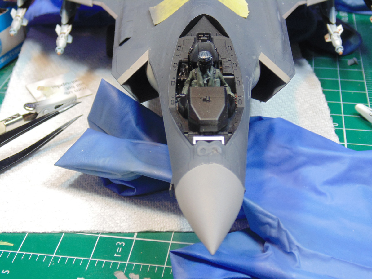
The cockpit and nose area are very complex. Inside you can opt to have just the empty seat with the supplied harness decals or the painted figure.
First, the highly detailed ejection seat parts must be filed or sanded for optimum fit. There are eight different colors which go into this mini model, adding an even greater depth of detail. Here’s a tip, for the ejection loop and green tank. Let the base color completely harden overnight. This will ensure that the Tamiya Acrylic Paint X-18 semi-gloss and XF-1 flat black will not mix with those base colors. It’s important because you can easily see both parts.
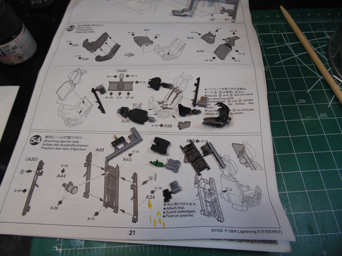
There are decals to go on still, but get the model put together and let it dry. It’s far easier to apply them after due to all the handling during the assembly. This is one of areas where wearing tight fitting Nitryl gloves is a must to consider.
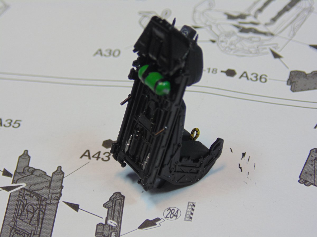
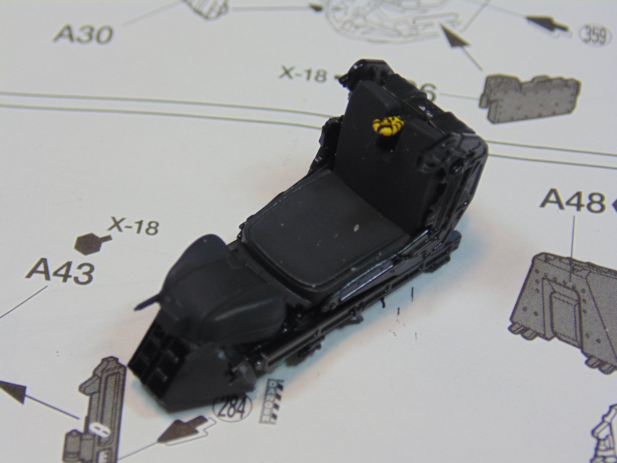
At this point, when the model has dried, you may wish to drybrush some metallizer or dark silver to pull out the detail of the rib framework and seat cushion. Even though this is a new aircraft I’m going to do just that, yet that’s much later after I’m confident all the components fit correctly. Sorry about the dust and debris.
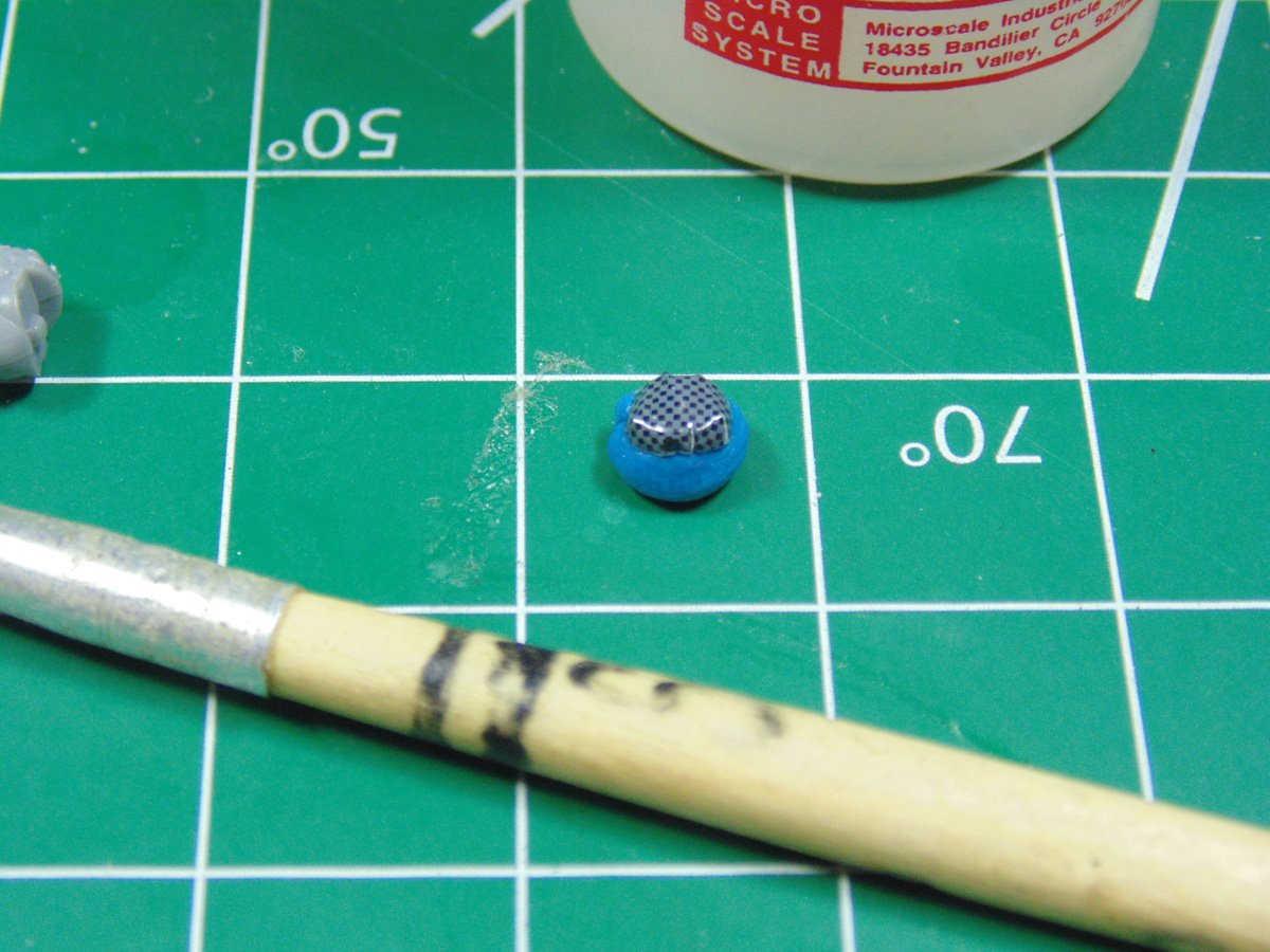
Now for the pilot figure. Again, a splendid piece of Tamiya artwork and engineering. The top decal was printed with slits to help it conform better. You can use Tamiya Markfit Strong 87135 setting solution for this job, yet I find for serious angles that Micro Sol works better. Regardless, let each application dry for a few minutes prior to adding the next coat. Some poster tac comes in handy to keep this part from moving around.
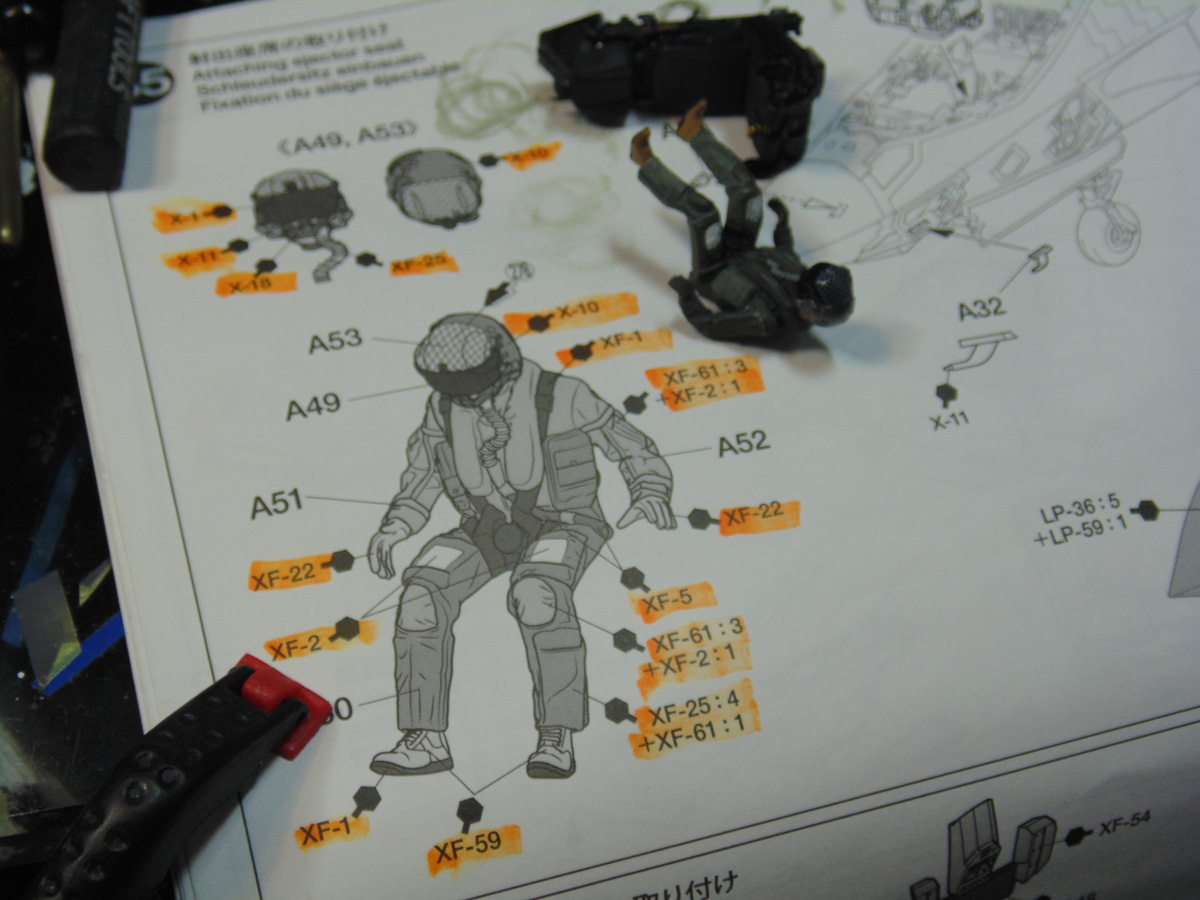
For the body, arms and helmet you’ll be hand painting the many different colors. Please don’t fret about this, it’s simply a process. You could choose to mask and spray some sections, but trust me when I say that would be frustrating. Use a highlighter marker to note the progress and give you satisfaction of completion. Consider buying from the store small mixing cups to make your life a lot easier.
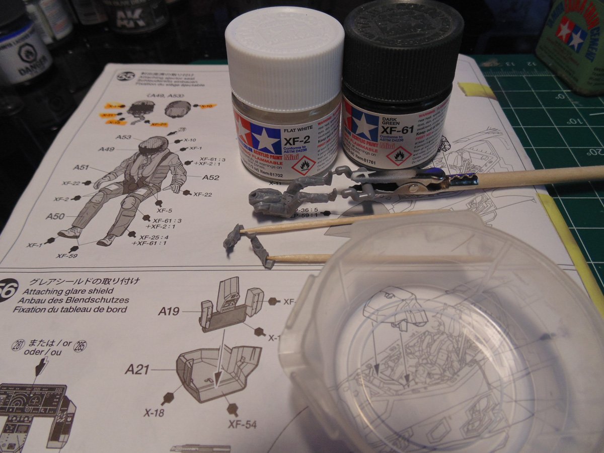
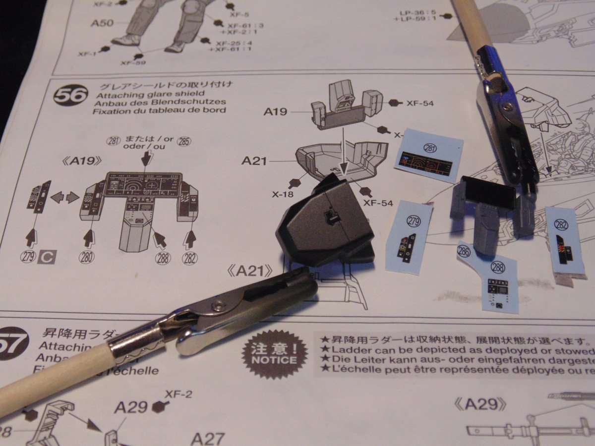
With the helmet assembled, painted and drying I took a break from that to spray the instrument subsection so it could have plenty of time to dry. Once again, you’ll have a worry-free decal application if your colors have lots of time to flash-off. Step 56 tells you to attach this part, but do not! Sorry Tamiya. There is a lot of fiddling around to come and you’ll need to see how the pilot fits with the seat and controls, as you’ll see later.
Here you can see the completed pilot figure. Put your mind on autopilot and go step by step color by color. The soles are super tiny lines to paint, so in this case I used a small black “Sharpy” marker. Just do the rims since you’ll never see the bottoms.
Fingertip oil should not bother you here. In fact, it adds a lifelike look. Give this a solid hour before the next round test fitting.
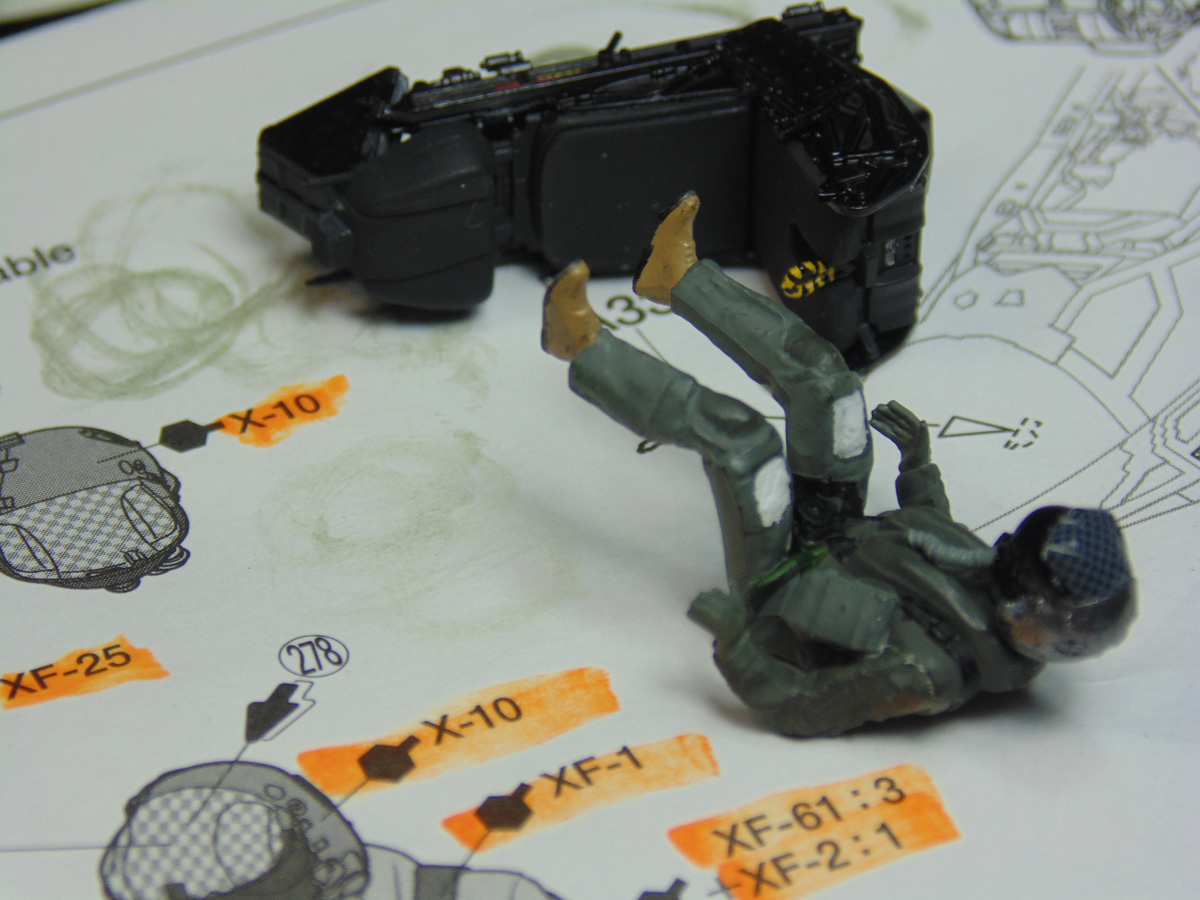
This round of test fitting shows that the control handles certainly do not match up with hands. The one the left in particular is preventing the pilot from aligning to the seat back. Plus, it looks dumb. I’m going to fix it.
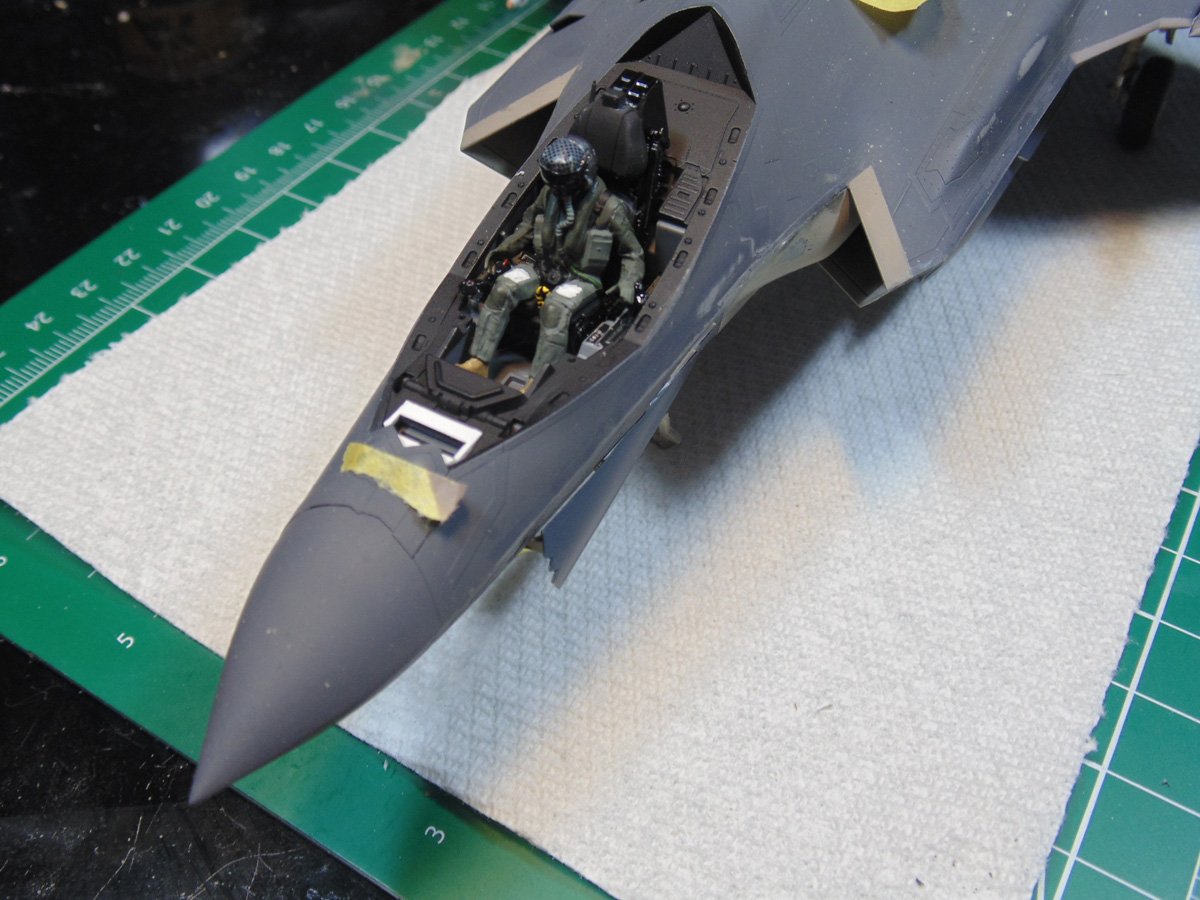
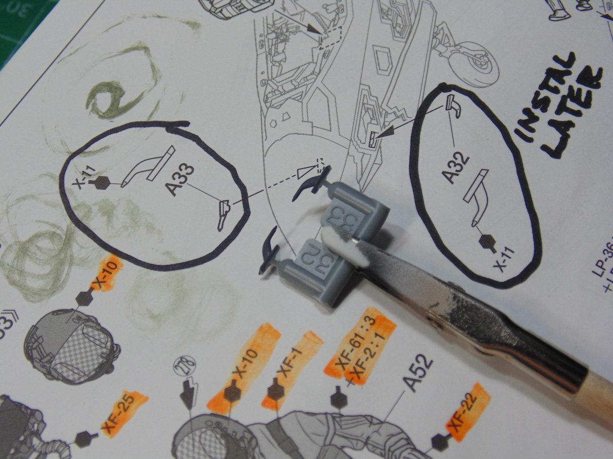
Before I begin fixing that issue, I’ll spray some parts to let them have enough time to fully dry. These sensors have a metallic and gloss tip and as you all know it takes much longer for gloss to dry. Wait until the model is fully completed before attaching them. This includes all touch-up painting and especially parts corrections.
The seat, pilot and glare shield are temporarily in place to figure out the changes to come. If you are reading these articles and have not yet begun the assembly I would strongly advise not adding these controls until now. They easily be slipped into place with the glare shield removed.
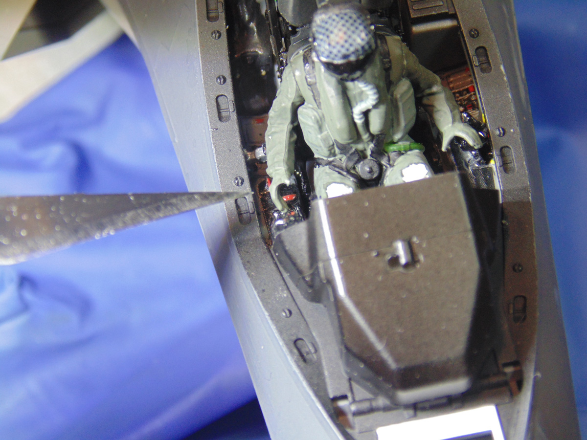
The right side control stick needs to, in this case, obviously come back. There are two ways to pull this off. You can un-weld it by adding Tamiya Extra thin cement, if you used that and methodically keep adding droplets until the dried cement softens enough. You can also very gently pull the part into place. The plastic slowly cracks, yet should still hang by a thread. The same applies for the left side.

Carefully remove the pilot figure and mix up some 5-minute epoxy and get it to the point where it’s beginning to harden but still fluid. I used a Glue Looper to scoop up some epoxy and filled the open cracks then quickly replaced the pilot. You can get these wonderful tools at Sunward Hobbies. Then it was just a matter of holding the control sticks into the open hands and waiting a few minutes for the BSI 2 part epoxy to cure. Again, keep the glare off so you have room to work.
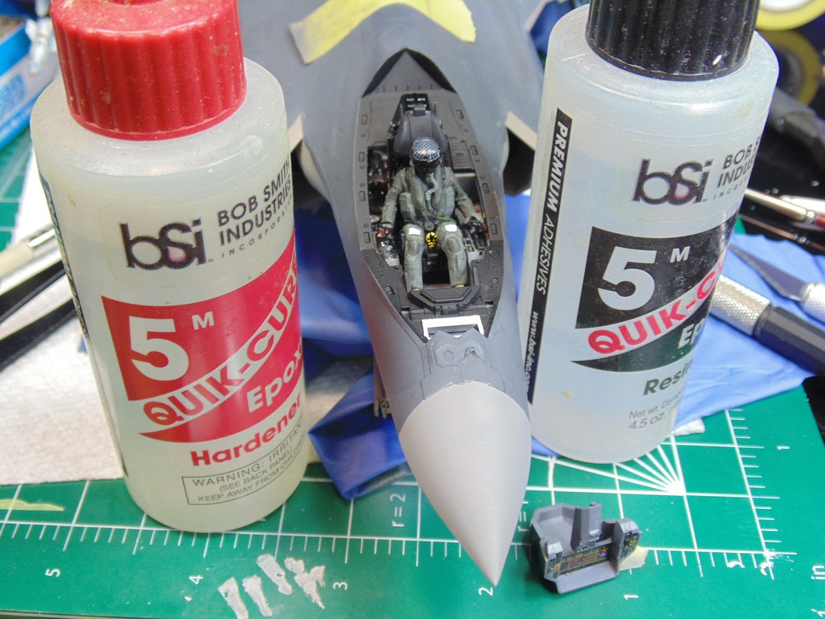
With that gong show over the nose has to be painted in a very special mixture of Tamiya lacquer paint. The LP-36 and LP-59 are so accurate, from the many photos I’ve researched, it’s scary…nicely done Tamiya. However, with all the complex angles of detail there is a goodly number of hours of masking to come. For short slight curves on a matt surface, I notch flexible tape. This tape forms a better smoother curve. Also, ensures it stays put and easily masked over.
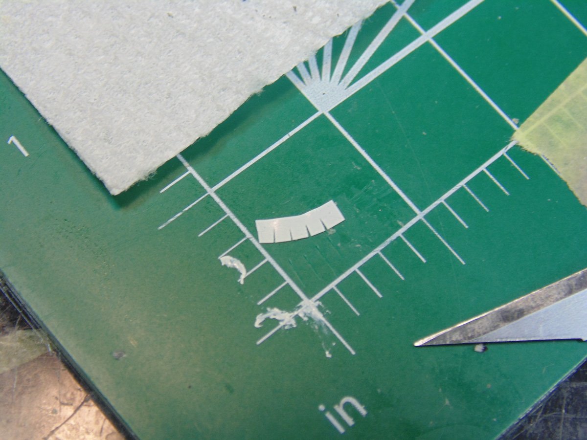
Use small bits of tape at the edges then mask them off. Here you can see the underbelly. Do not scrimp with how far back you go. To prevent overspray, I usually back about four inches since all my coats will be misted on to get the right effect.
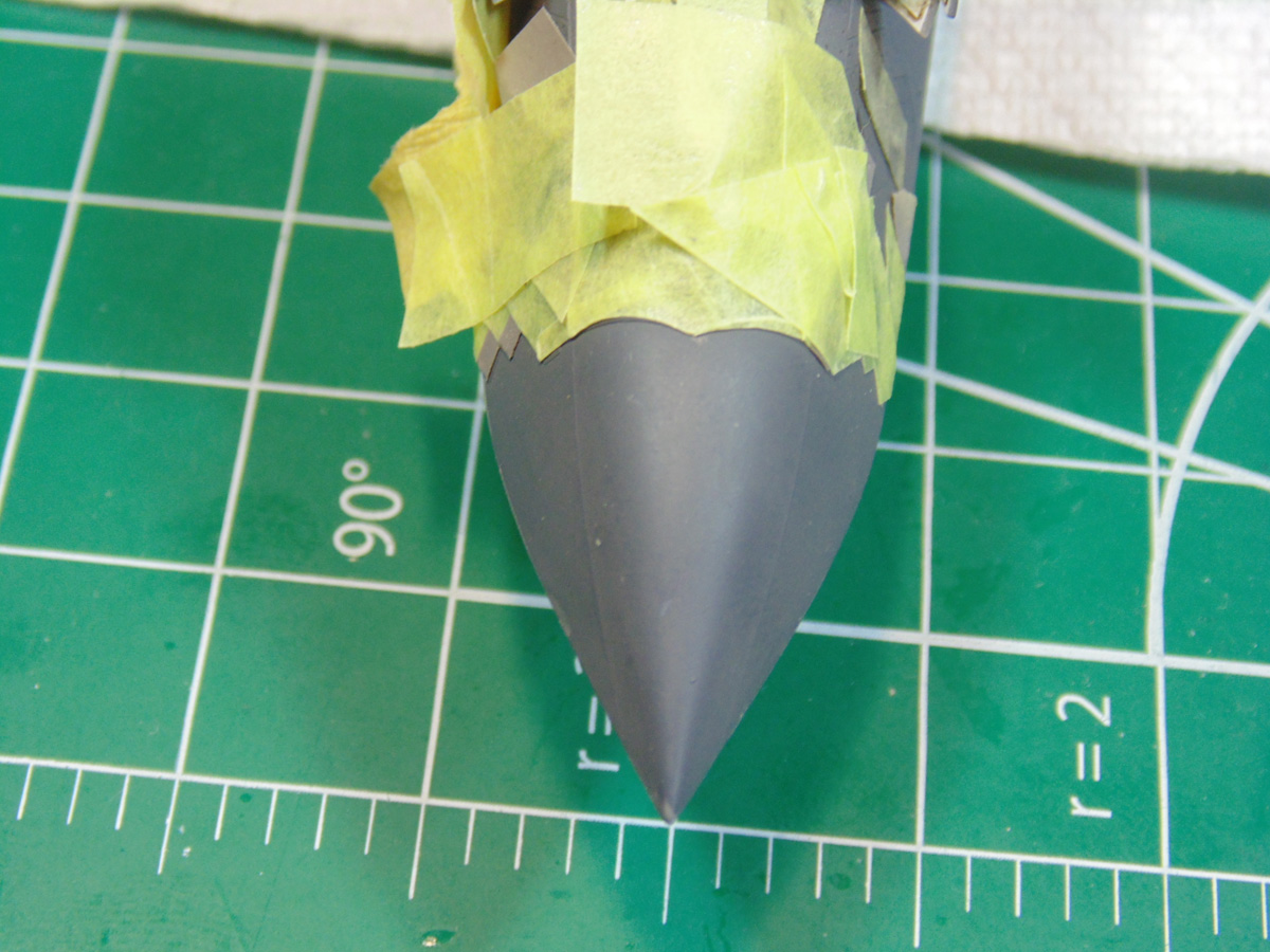
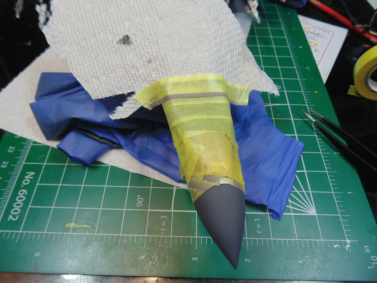
Here, I’ve removed the cockpit details so they don’t get damaged while the model is being masked. Sometimes a simple strip of paper towel works great. Now you can press down on the tape edges just in case some may have lifted a bit.
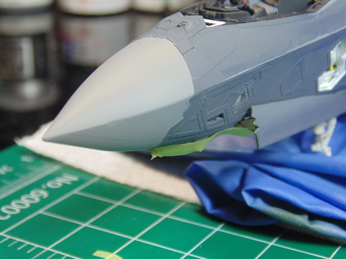
A few minor touch-ups and I’d call this area complete. That little ding is just a bit of flex in the metal during test flights. Seriously though, touch-ups are a part of the process. With a super fine brush, you can easily look after them and even you’ll forget they were done.
In Step 57 you can have the ladder sealed up or exposed. Naturally I wanted to show how the deployed version. This section was super easy to assemble, paint and get ready for installation. Moreover, it adds a huge amount of detail to the look of the replica. Once again, wait until the model has been completely fixed of any and all touch-ups.
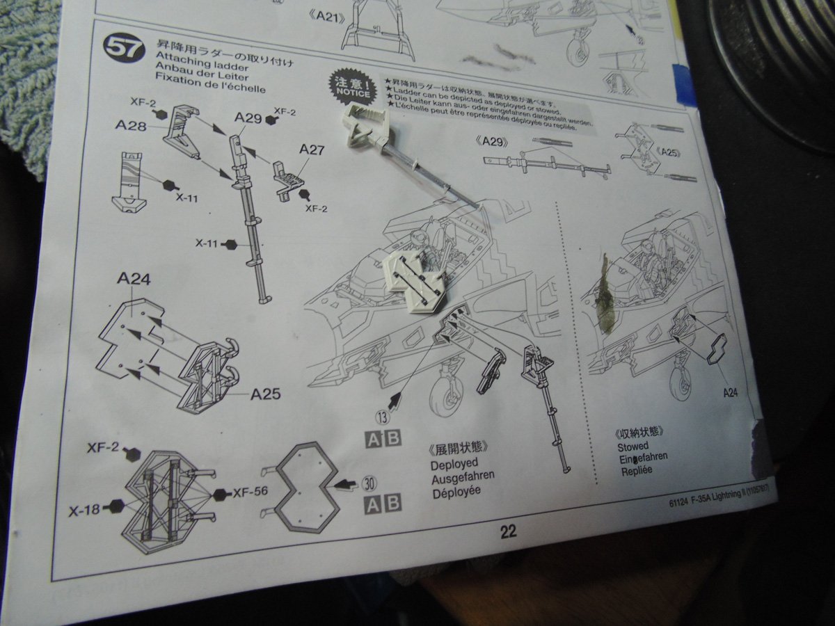
And here you have it. It’s truly hard to fathom the amount of work that went into designing this Tamiya model. So much so you’d almost think it was a 1/32 scale. Sure there’s a bit of work involved and many yours in the making, but as I’ve said from the get go… be prepared to hear lots of glowing words kindly sent their way.
If you have any questions about the products or methods used in this article, please feel free to ask the staff when you pick up or place your next order from Sunward Hobbies.
H.G. Barnes is a former voice-over artist and retired sales and marketing professional. He’s the author of two large volume science fiction adventure romance novels with many more in the works. For well over 40 years he’s been building scale model replicas and now does commission work for clients in Canada and the USA, plus completes projects for companies in Asia and Europe.
Actuellement, HG est impliqué en tant que rédacteur associé avec les chaînes de magazines en ligne de KitMaker Network.
