Tamiya Bismarck Battleship 1/350 Scale Kit 78013 – Part 6
In this Sunward Hobbies article I’ll continue with Part 6 of the build of the Tamiya 1/350 scale model of the German battleship Bismarck (items# 78013).
We are nearing the end of all the major construction on this huge model; thus, I’ll be showing you ways to make this daunting process glide smoothly.
It’s critical to test fit the section as many times as you need. Grasping the runways, just aft of the funnel, to remove and replace this section will help prevent snapping off the small parts. Also, try to have an open area to work. My writing studio was never set-up for this size of project, so I used the dining room table.
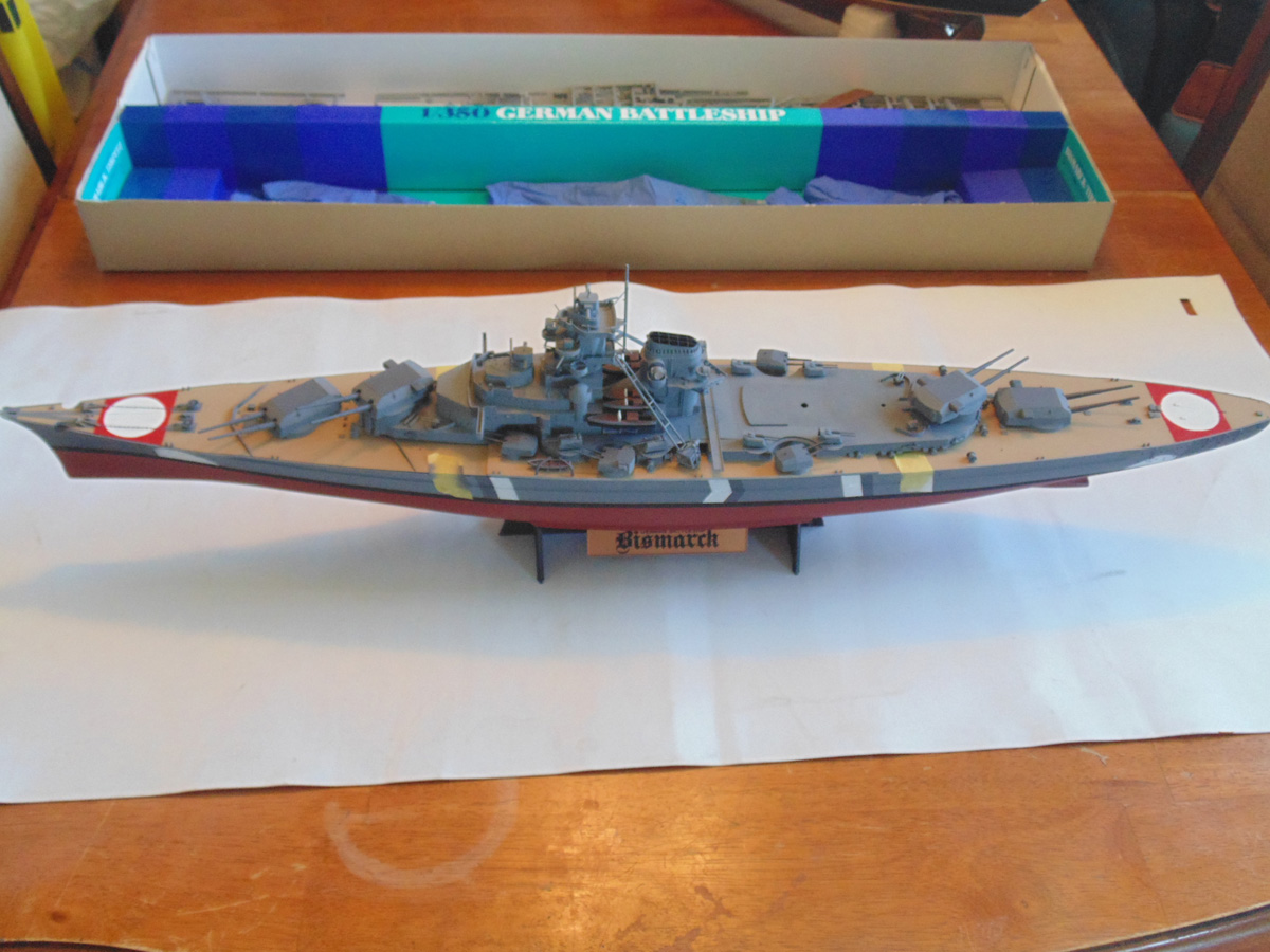
After taking a break from the test fitting there are plenty of other little, yet important, tasks to finish up. Painting very fine detail can seem intimidating, but it doesn’t have to be. The lettering on the stand’s name plate can be pulled off with some patience and paint retarder added to your colour.
Putting the smallest dab on the edge of your fine bush then placing it on a forward point to be painted works well. Then literally pull the paint back. It takes a steady hand, but you’ll become familiar with the process quickly. Get as close to a 90-degree angle as you can. Sunward Hobbies have all these brushes. Just ask one of the staff to help you out with the right type for the task.

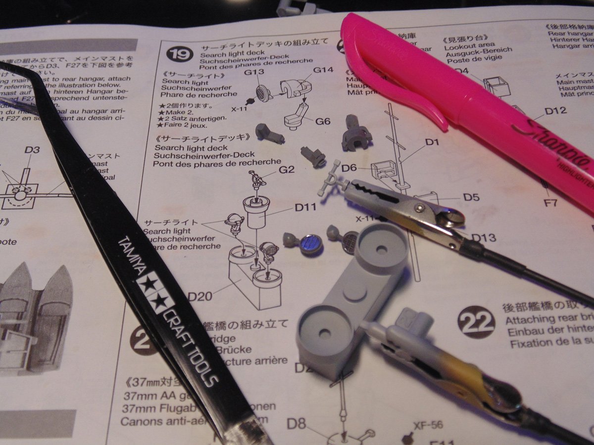
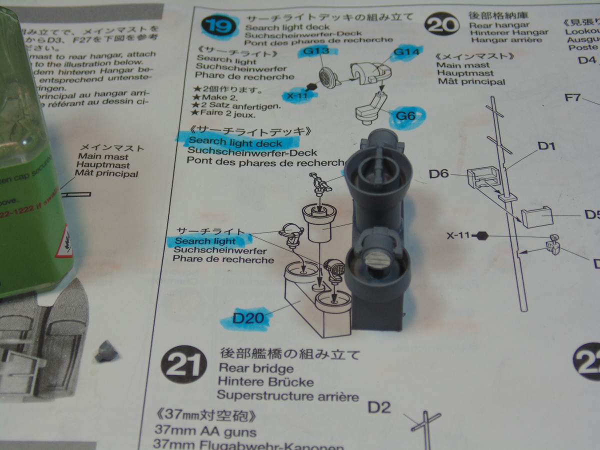
Step 19 is a breeze since the parts have already been primed. Here again is the AK Interactive Super Chrome 9198 product for the searchlight glacious which David recently did a video on. You will have to remove any paint and primer from the insert openings to get the arms of the lights to fit. It’s much easier to do that than to scrape the flash from the connecting pins.
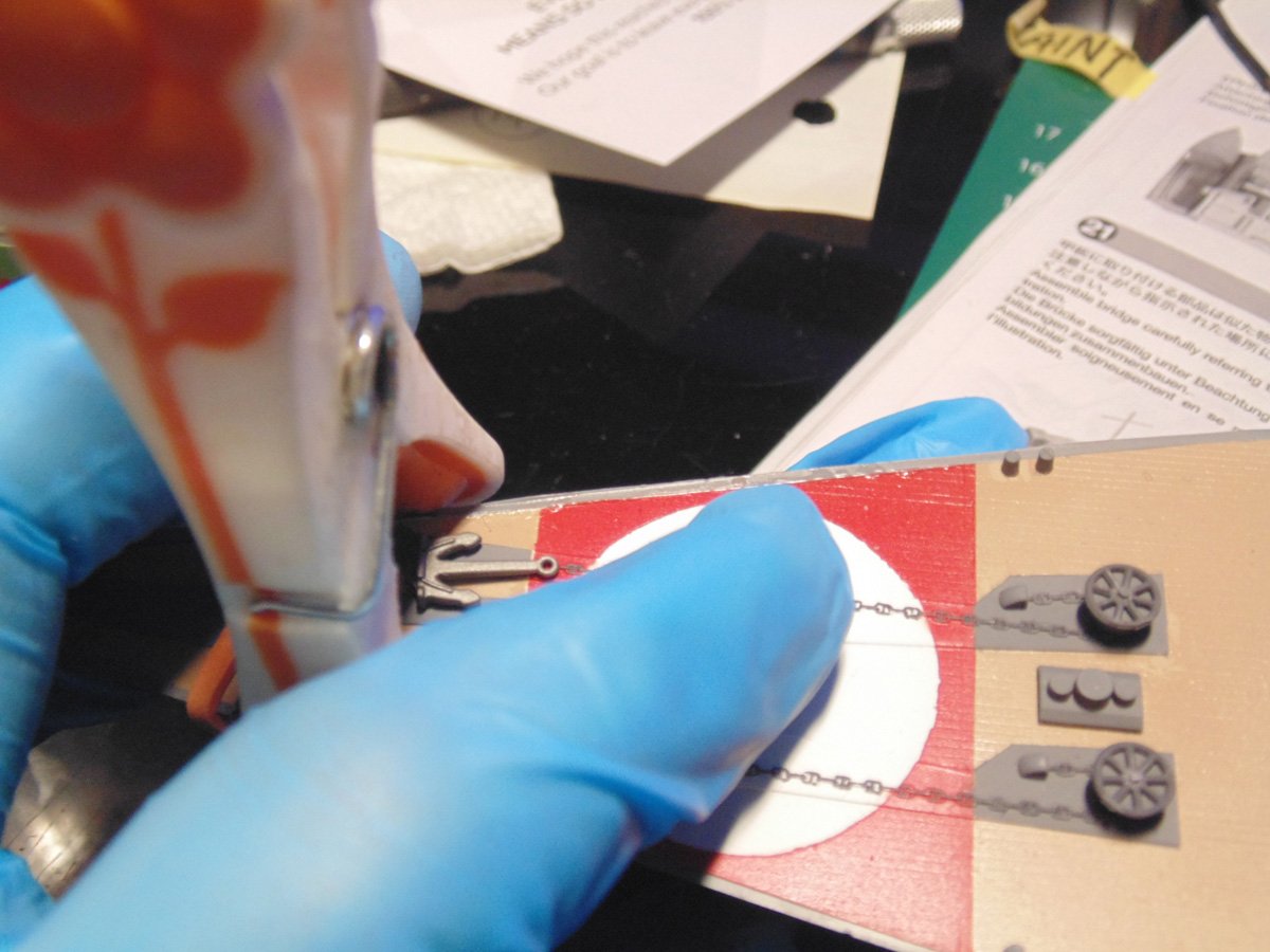
When installing the front deck press your finger down at spots to ensure the fit is tight. You’ll be able to know this by the slight sound of plastic on plastic. Use a clamp and a rubber band at the tip of the bow and let it set up before moving a few inches back. Even though I’ve clear coat protected the hull gloves were still used to prevent scratches.

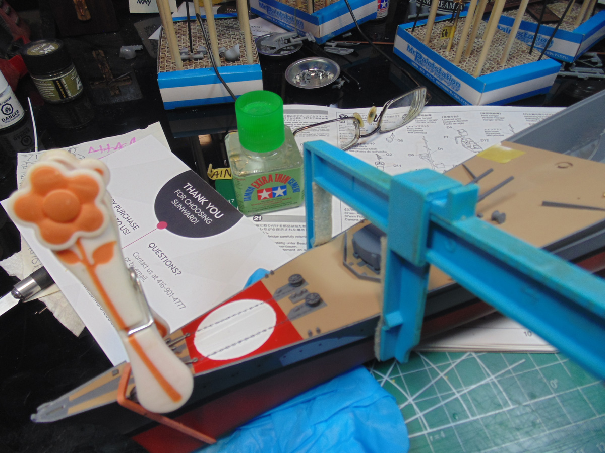
Now that I know the forward section is battened down you can “walk back” the gluing process. Use a clamp to draw the sides together while pressing down on the deck. You don’t need a lot of pressure, but hold each point for a minute. If it pops up, simply add more cement and hold it for a couple of minutes longer.
Once the forward deck component’s have somewhat stiffened you can add some more Excel Hobby clamps and move down a little more. You’ll be able to feel where to add more cement and clamp. There’s also a noticeable plastic creaking sound to help you out.
It is crucial to get this section placed right because it affects the fit of the other two deck parts, hence why all the test fitting. Don’t scrimp on the cement and use a heavy weight to gently force the part down. Here, I’m using a common jewelers anvil to assist in the process so I can move on to other steps.

Adding a slight amount of pressure at the forward heavy turret is also wise. The plastic is very thick and because of that there will be some minor warping which you will need to address. It isn’t catastrophic, yet if you want the right look then you must invest some time, trust me it’s worth it and fun.
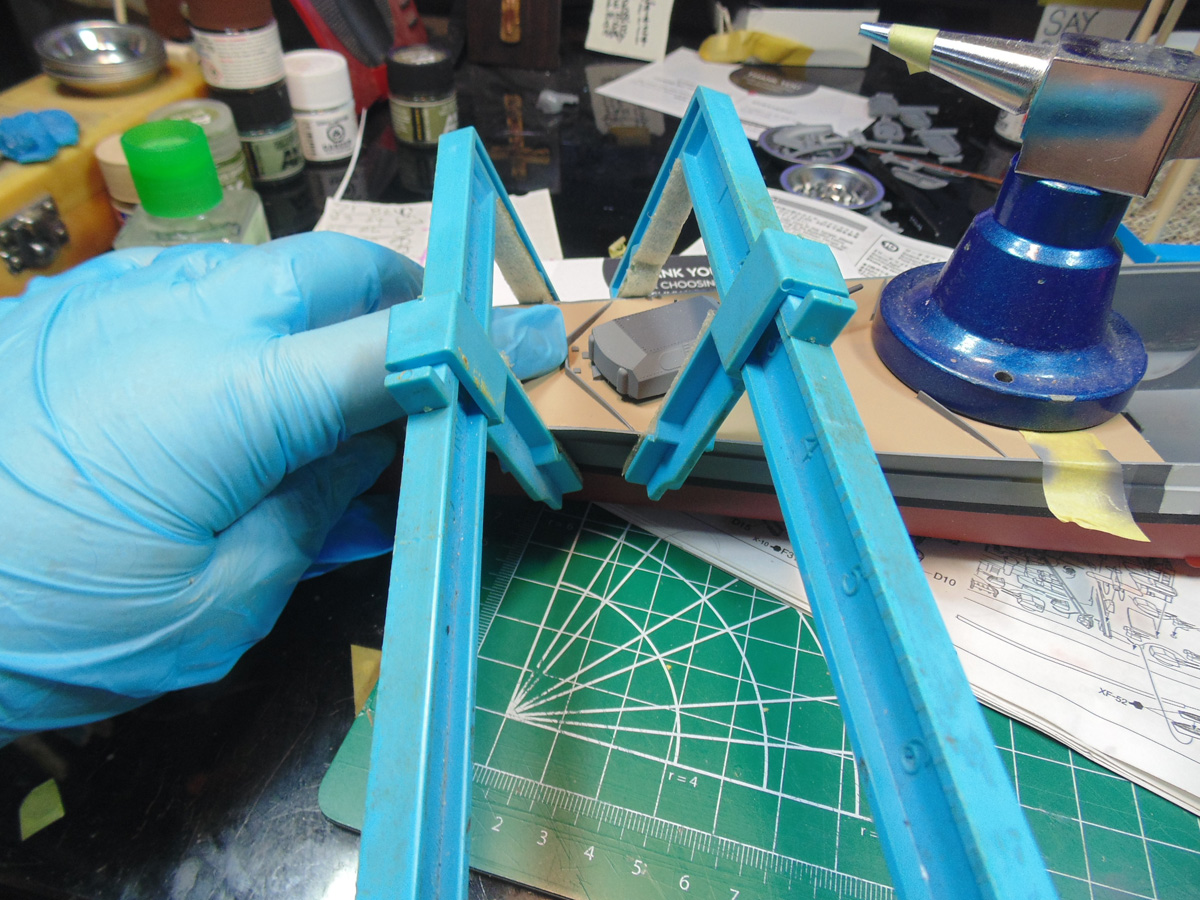
Once the cement has seeped in all the seam lines it only takes a minor bit of persuasion, and some hobby tape, to get it to stay put. I know I harp on this, but pick up some rubber gloves from the store. On a model this size finger marks are easily noticed.
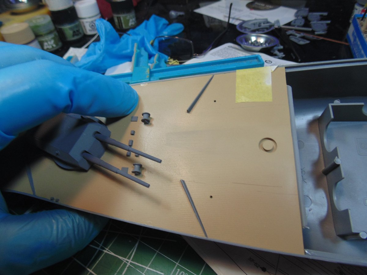
Please go back through the previous work and ensure the deck plate is solid. You can always do little paint touch-ups here and there later. The shape of the entire hull is determined by the end sections and affects the mid-ship part.
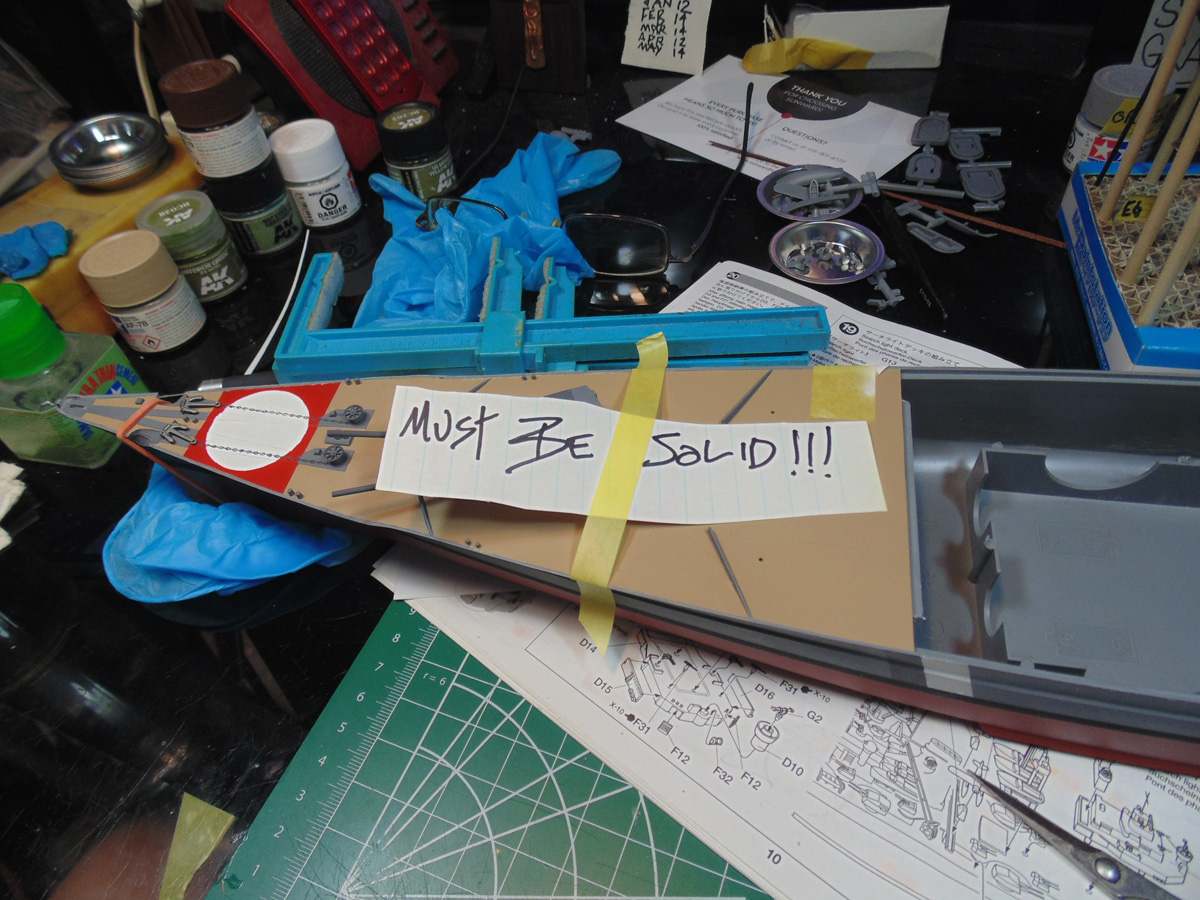
The stern plate requires the same amount of attention. Make sure not to shave off too much material from the edges though. The cement will melt the excess and help conform the part to the hull. Be sure to use some clamps to draw in the sides of the hull.
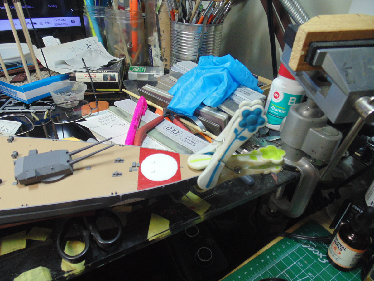
You’ll need to rinse and repeat the process for the midsection of the stern plate as was done on the bow. Be mindful of the small parts added. Their connection points were super skinny and fragile. Two broke off on me were an absolute pain to get back into place.
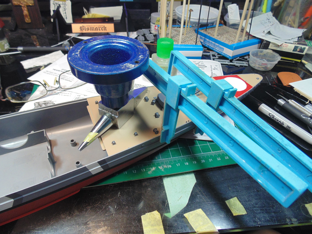
Now that the forward and aft plates are firmly in place you can now look after the slight rise of the mid deck section. In nineteen seventy-eight this area was meant to be removed in order to swap out batteries and parts. The fit was never that important in those days, but being this is a static replica which won’t be going in a kid’s pool or bathtub the fit issue has to be fixed. Use a curved Excel blade to carve away a half millimetre of plastic from the resting lip. Be prepared to connect one end prior to moving to the next. On this model the mid section rocked back and forth. And, again, use clamps to pull the sides into the edges of the deck plate.
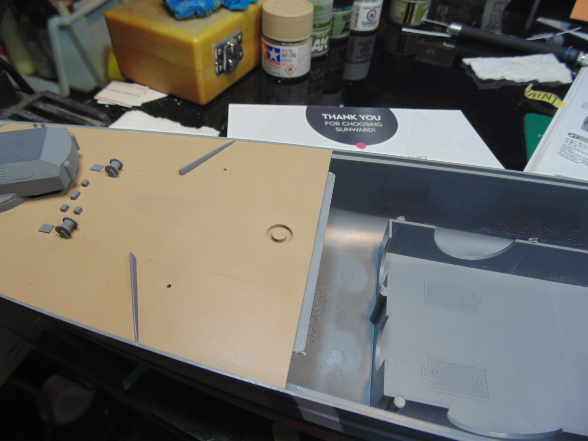
Now I’ll finish up Step 19 and to the highlight painting points later. It is a small section of the replica, yet adds to the overall detail Tamiya put into the model. Use your fine needle Excel tweezers to place the parts and you won’t have a problem.
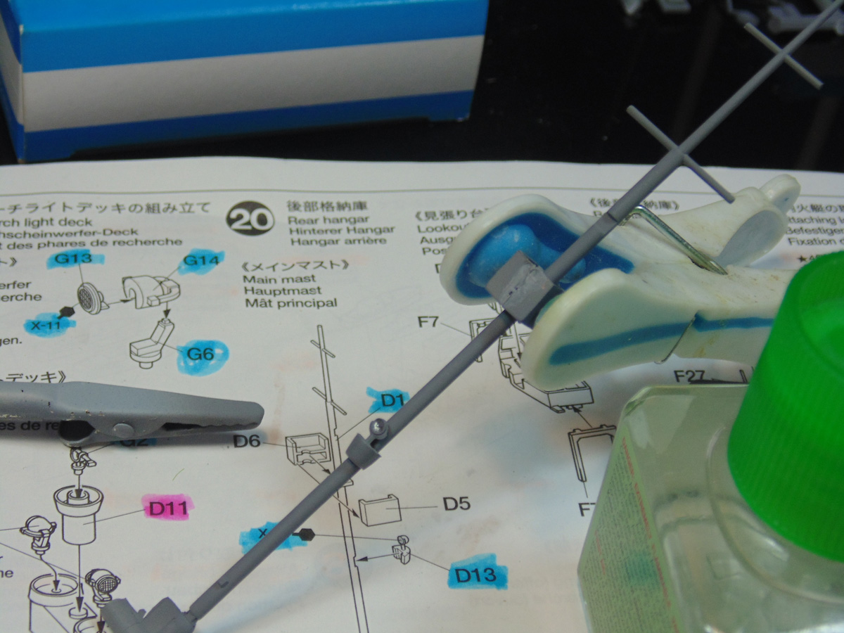
The “crows’ nest” in Step 20 has to be finely sanded to fit right on the mast. Consider using a file. Sunward Hobbies have these in stock and they work great for all sorts of projects. Test fit these halves repeatedly until you’re happy.
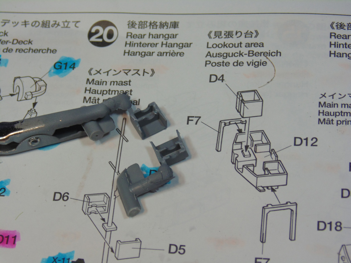
After you join the two halves clamp them. Now your model may be different, but this one has bends inward on the edges. An easy fix, as you’ll see later. Also, note the AK chrome on the light standard. I can’t tell you if this is accurate, it just looks nice.
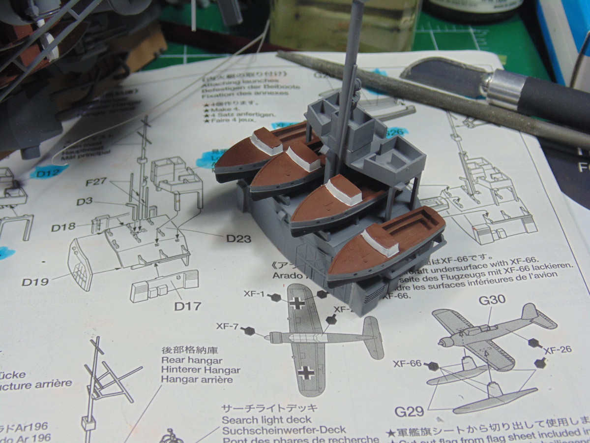
The boat launches in the mid deck area are much like the others. They need to be primed along with test fitted. Again, don’t scrimp out on the cement. Any excess ooze can be removed later or used to help seat them in place.
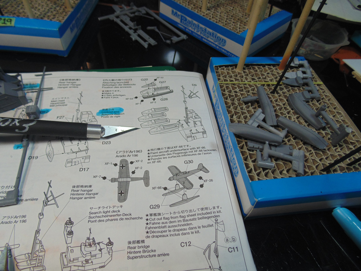
It’s up to you if the insides should be filled to make the decks look flat. Remember, you’ll be hard pressed to even see that level of detail on a basic build such as this one is. Focus on the obvious, in my opinion, to make your project stand out.
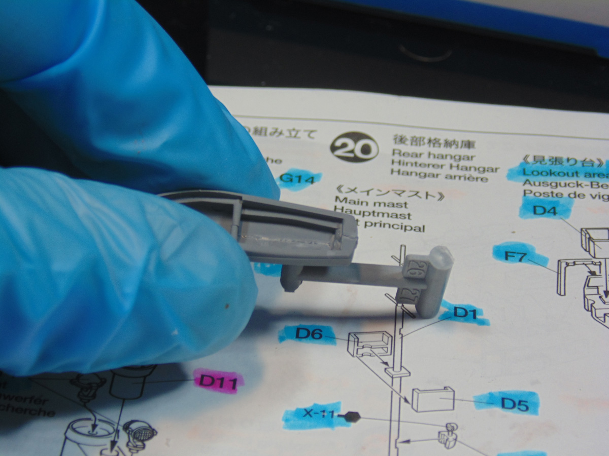
The parting lines of the crows’ nest were filled and need half a day to dry properly prior to sanding. The rear hanger section must have the inside edges of the plastic honed down by one half of a millimeter in order for it to fit over the raised plastic on the deck. It is way easier to shave away the material from the inside of the sidewalls as opposed to the deck.
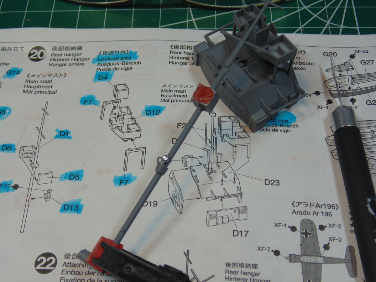
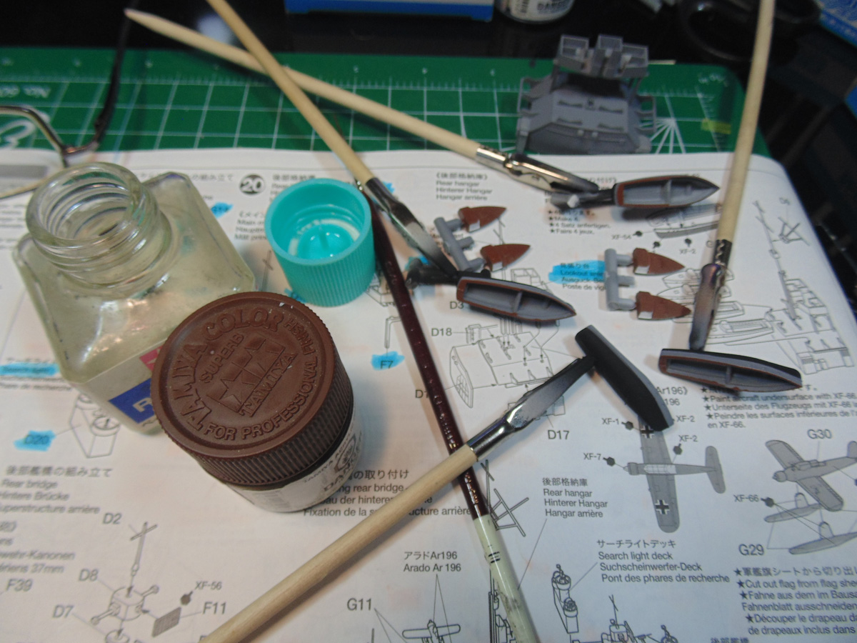
To achieve a crisp look for the boats, please consider masking off the hulls and airbrushing for the Tamiya XF-1 flat black. The hobby tape will cling well to the primed and painted surface with little pressure, plus the result looks great compared to hand painting it.
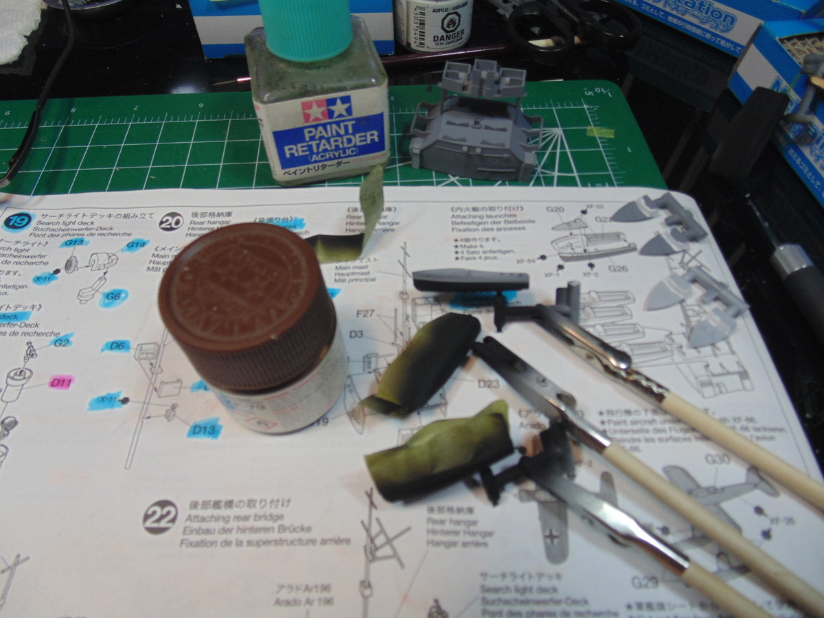
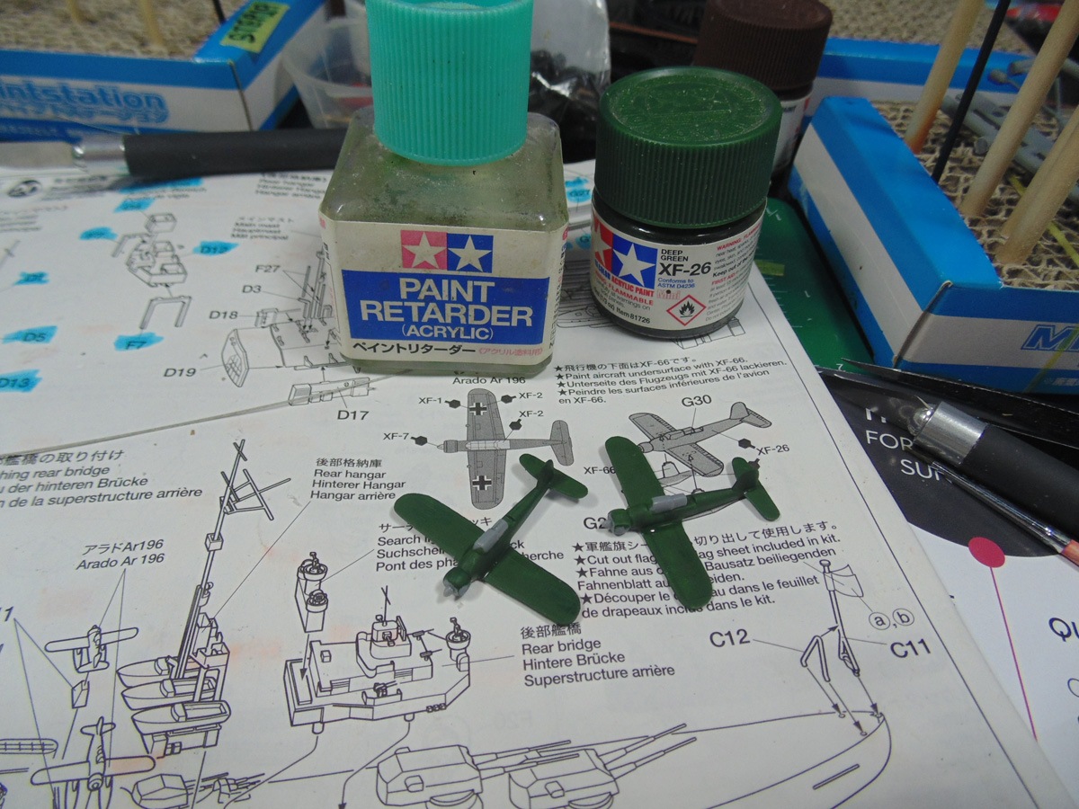
As you’ve seen I blend a drop of retarder in the cap of my paint jar. The pigments self level but take longer to dry. The retarder also turns flat paint into a semi-gloss look. A light dusting of flat clear coat will knock that down, should you choose to have that appearance.
In Part 21 the holes in the base of the aft bridge need to be reamed out slightly. You can pick up a round file from the store to get this done. The thick pins are difficult to get at, hence opening the holes a bit is far wiser and more convenient.
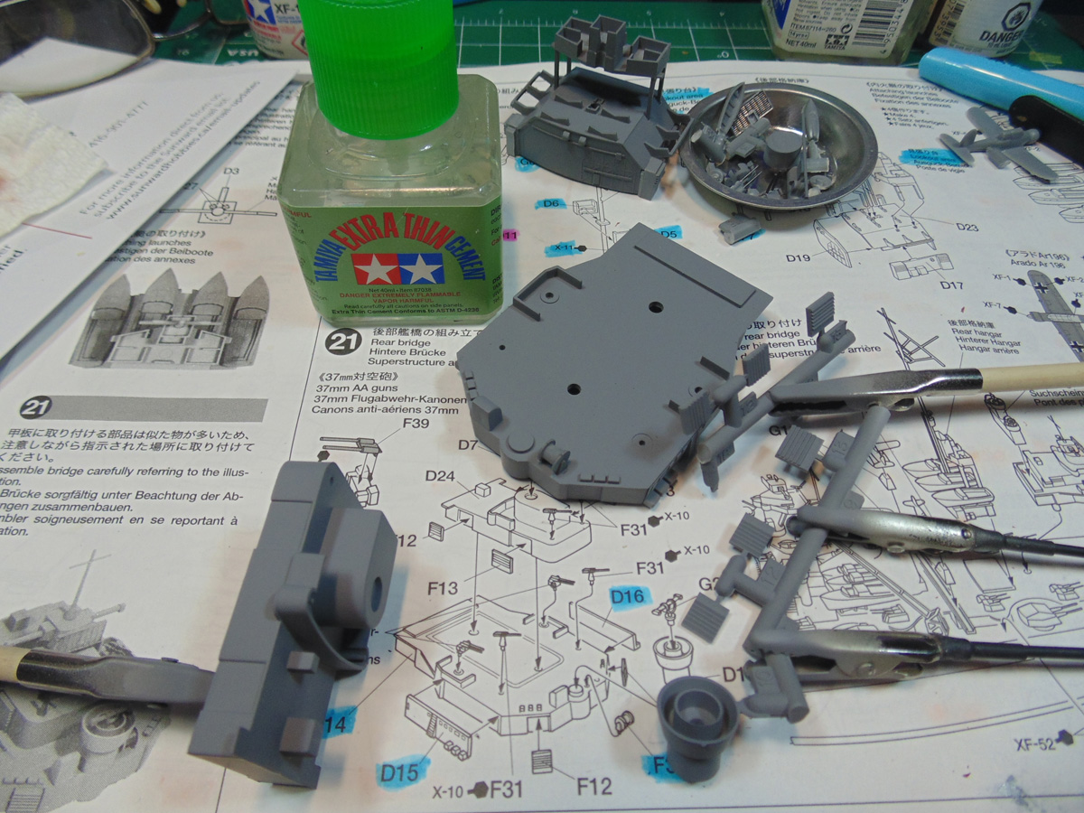
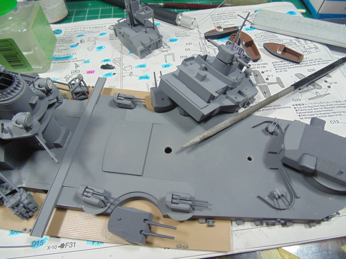
I spruced up the look of the radge finder and radar parts with some Tamiya X-10 Gunmetal. Even though this is a basic build you can still do some little things to add more life to your project. Put on the lower parts of this superstructure first, save for the guns, prior to adding the upper pieces.
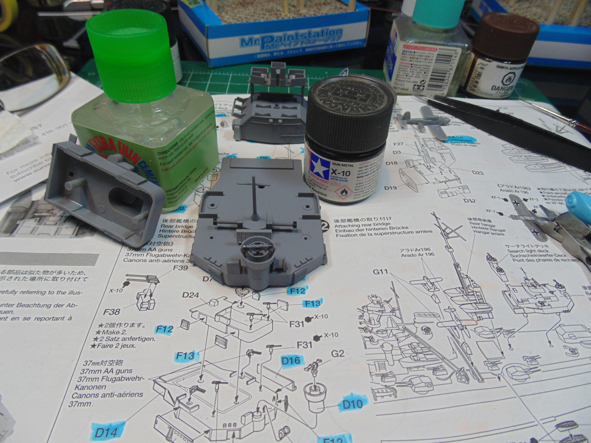
The upper radar section of the aft bridge must be clamped; however, you can save yourself some time by filing level the very base. Note the chrome on the collector, again one more small detail that helps this replica pop.
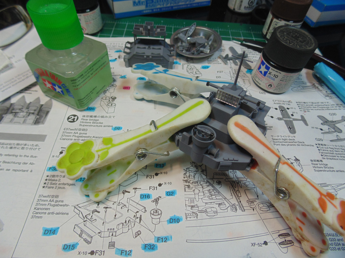
Now I’ll switch back to the launch boat and hangar area. The resting places at the hulls are not shaped right. Scrape the paint and primer away from where these hulls sit. I wouldn’t fret about removing the paint from each hull to have a decent bond. The cement will take care of that.
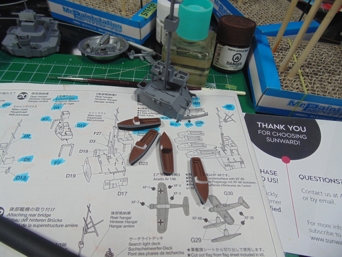
Due to the number of the many fine parts you must be extremely cautious where you place your clamps at the aft bridge. The subsection on this kit had a slight warp which needed to be corrected, even after filing and sanding. It wasn’t much, but I didn’t like the gap.
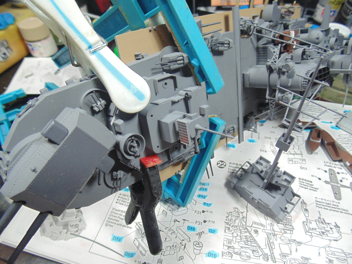
I would leave the launches dry for a good eight hours. After they harden in place you will need to press on them to get the hangar to seat flush with the deck. After that is done you can do your desired touch ups.
These tiny Arado aircraft were airbrushed with the XF-66 Light Grey on the belly but had to be hand painted the XF-26 Deep Green topside. Use the advice mentioned for the name plates to get crisp edges. Don’t over flood the wings since you’re going to be painting the flight insignias.
With most of the big items attached to the middle component you can finally attach it. Condition the mating surface of the section that falls on the forward deck area with cement. Just run the wet part of the cement applicator along the edge and wait a few seconds. Next, slip the part into place and flood the edges with more cement. Clamp it down and hold any misbehaving spots. It might take five minutes or but it’s so worth it.
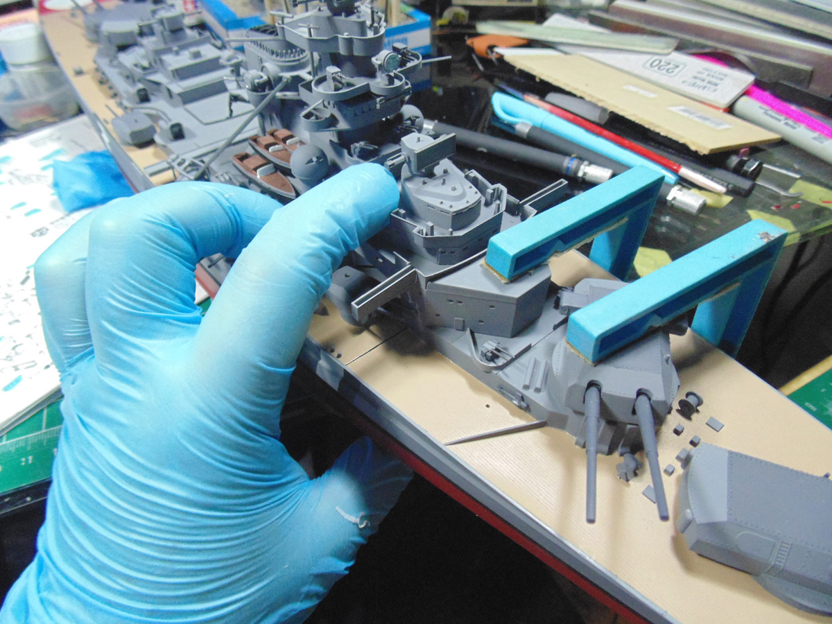
Here you see the warp in the middle deck area. It has to be left alone until the forward part of the deck has completely dried and hardened. Keep in mind, you’ve already test fitted this section repeatedly, so it’s just a matter of patience to get it nailed down.
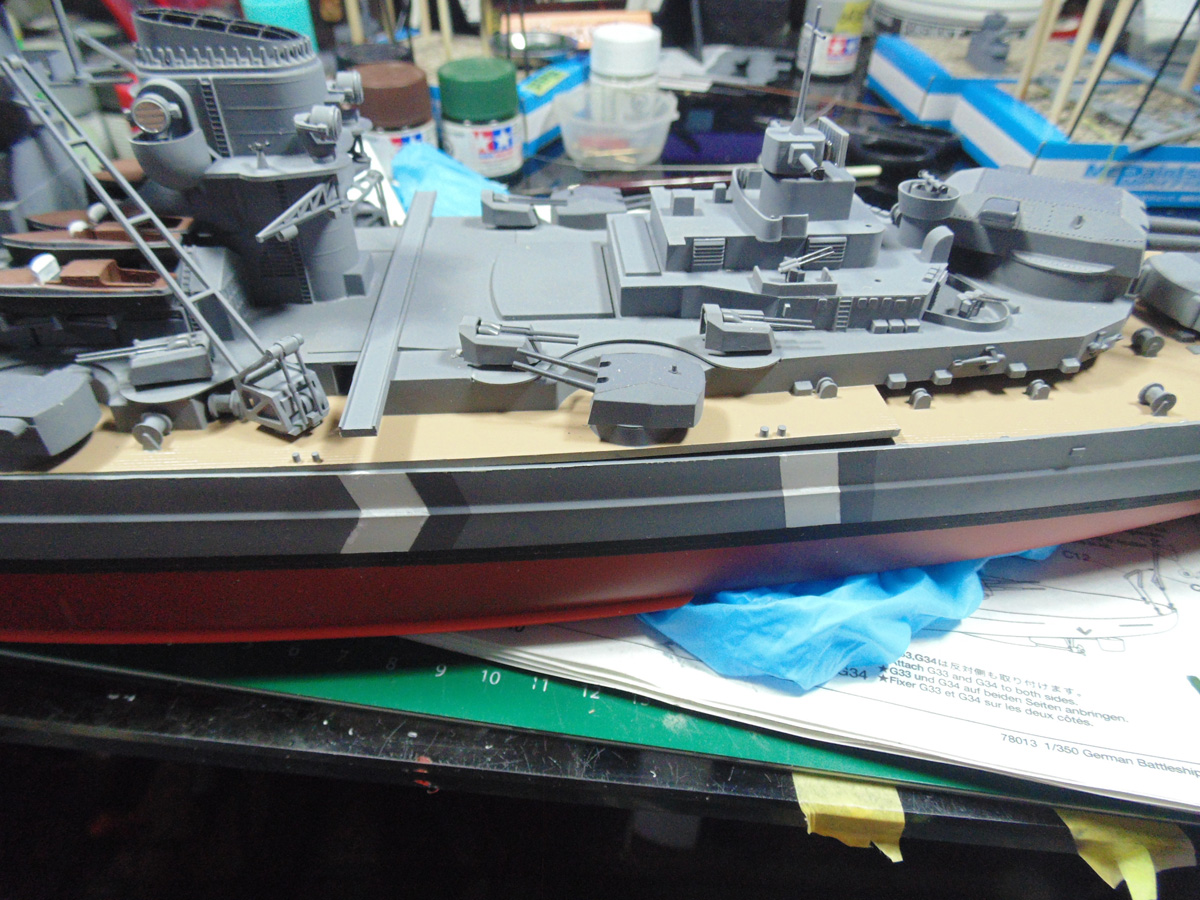
Use a sponge in the middle of the midship to assist your large clamp and make certain there is some soft material to protect the hull from being scratched. The blue block is common packaging material, regardless employ what’s on hand to force the part into place.
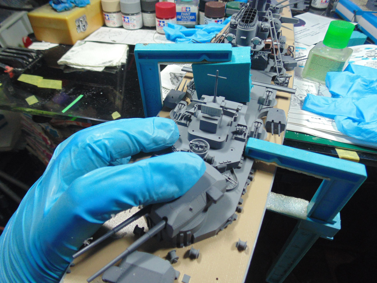
Be super careful with how much material you remove from the connection points of the float pods to the wings. These little flyers are well crafted and need hours to harden for the upcoming fine painting. Let them sit to one side for six hours.
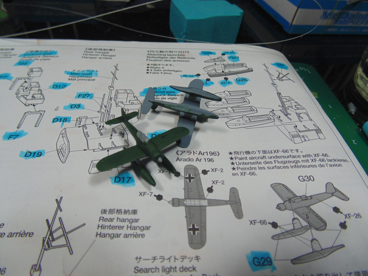
The aircraft sit in the launch runways very well. The amount of detail is something else! The hand painted flight wing insignias were done under a magnifier, yet you can do this too with a fine brush and then run some deep green along the edges to hide any over-brushing.
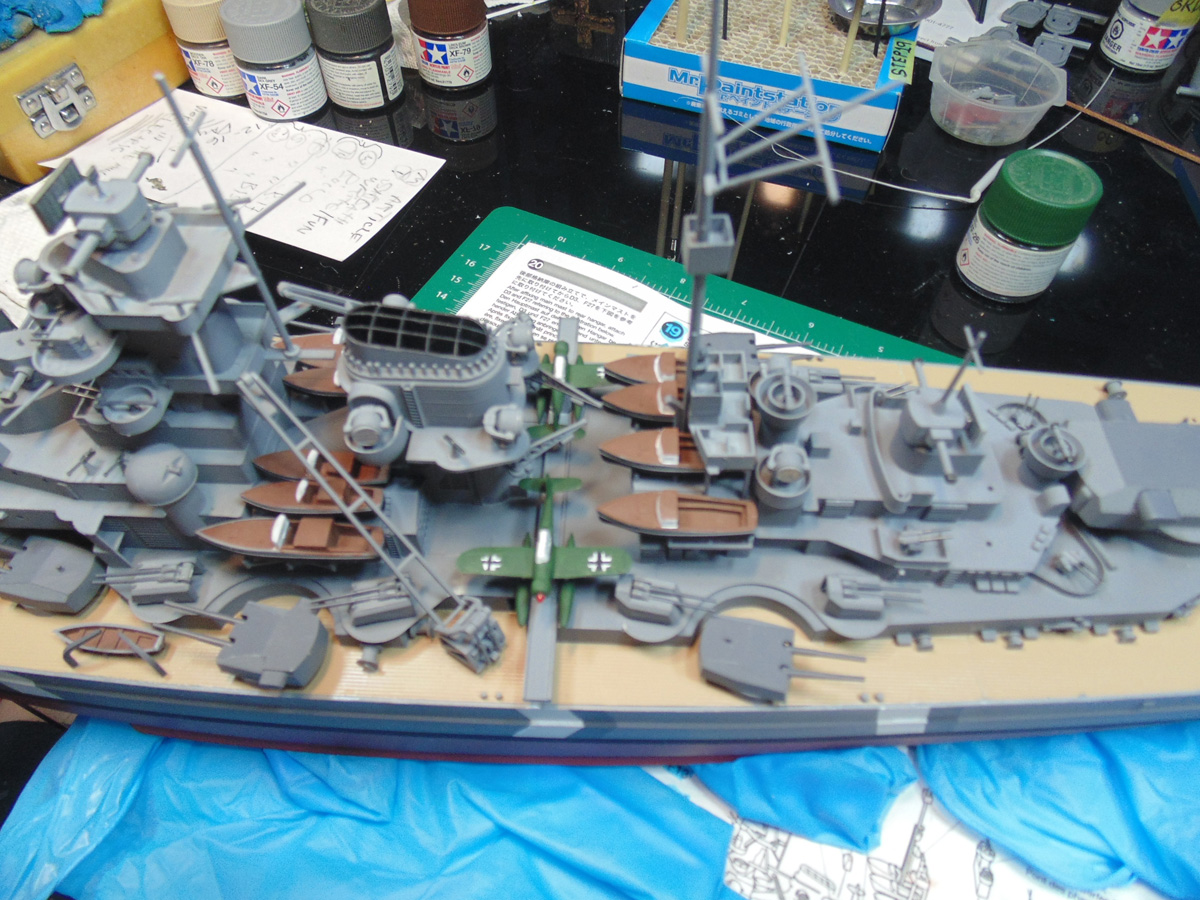
Here’s some shots of the current progress.
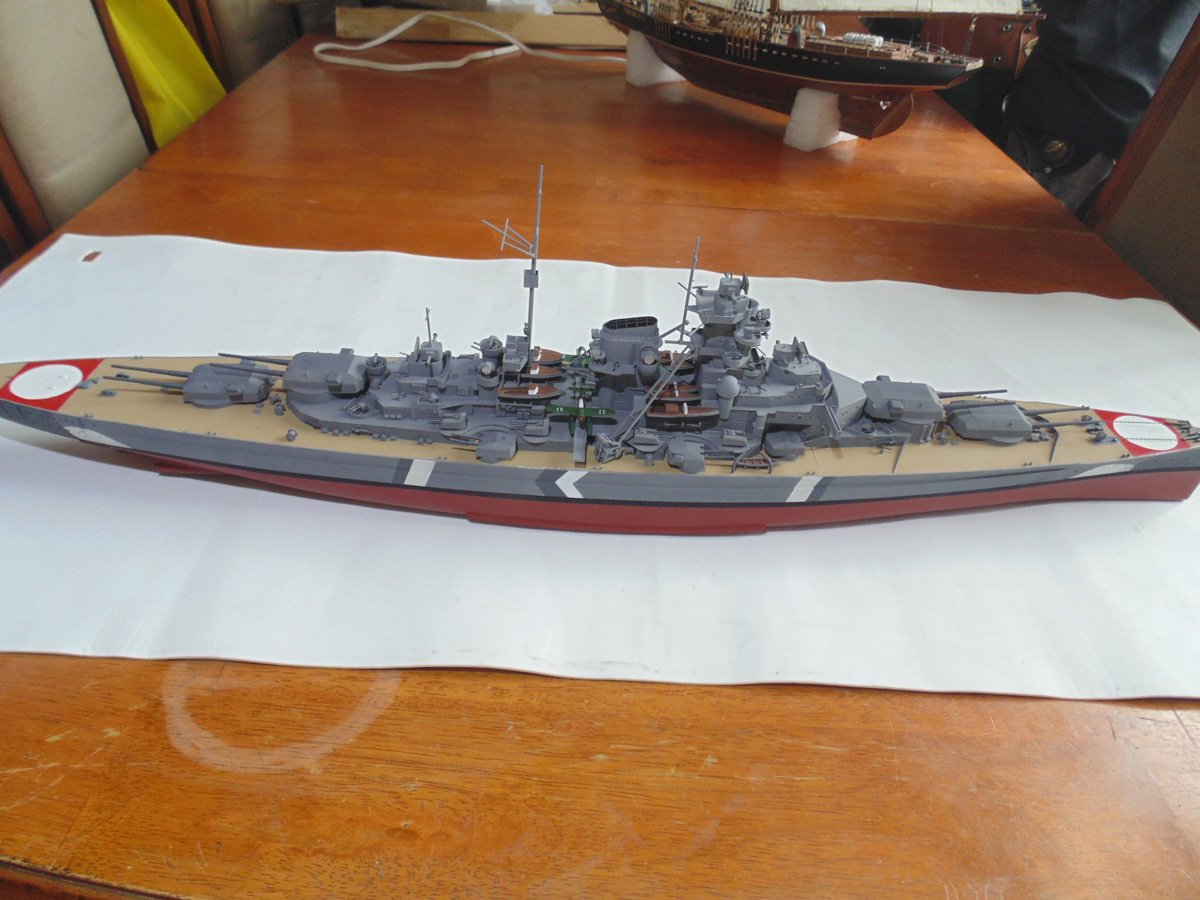
Please excuse the over lighting. I wanted this shot to show you the details. For a kit from the late seventies it sure is measuring up to today’s standards.
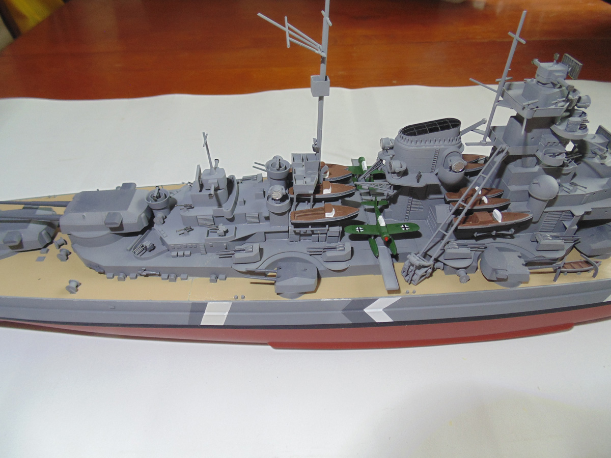
Now for a beauty shot. You will definitely enjoy these Steps on page 10. Sure, there’s work to be done of course and that work will provide countless hours of viewing enjoyment.
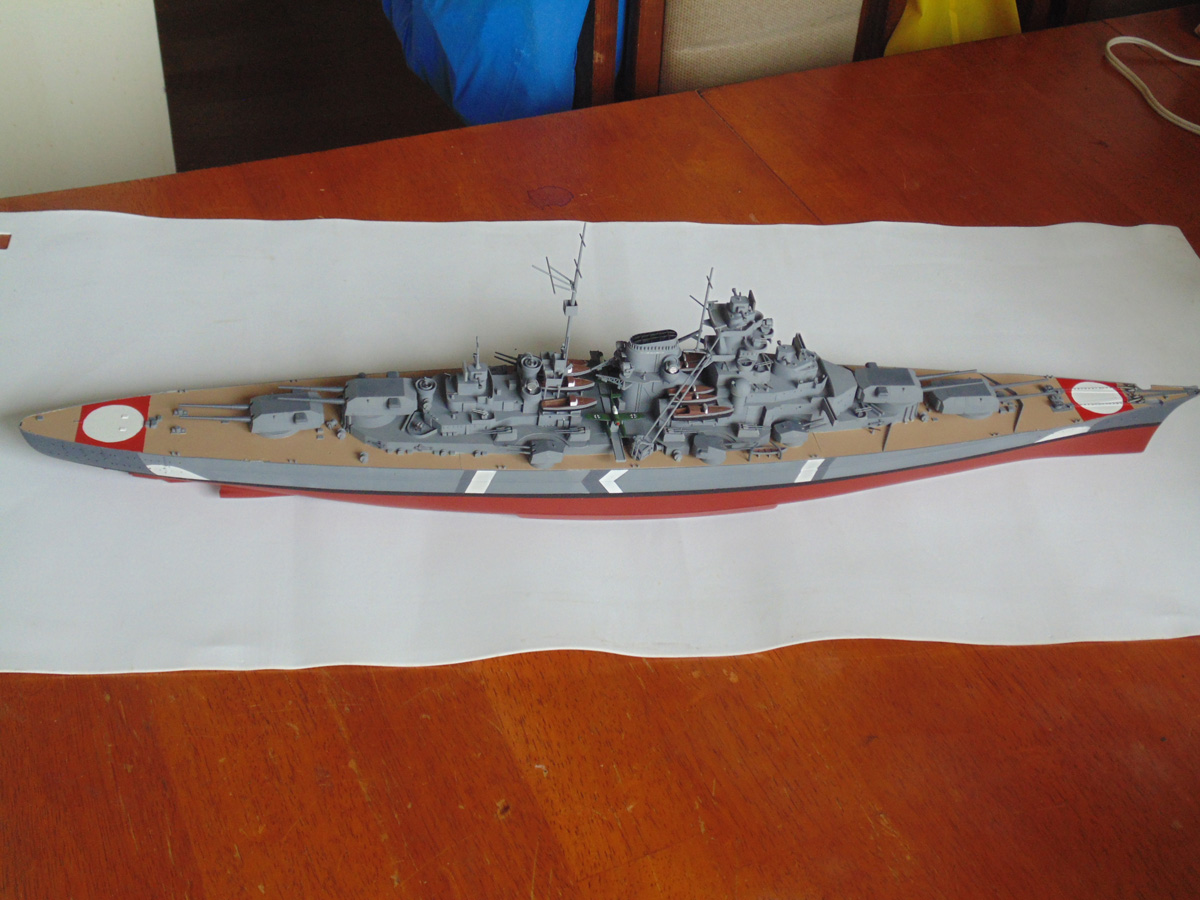
If you have any questions about the products or methods used in this article, please feel free to ask the staff when you pick up or place your next order from Sunward Hobbies.
H.G. Barnes is a former voice-over artist and retired sales and marketing professional. He’s the author of two large volume science fiction adventure romance novels with many more in the works. For well over 40 years he’s been building scale model replicas and now does commission work for clients in Canada and the USA, plus completes projects for companies in Asia and Europe.
Actuellement, HG est impliqué en tant que rédacteur associé avec les chaînes de magazines en ligne de KitMaker Network.
