Building Tamiya Tank Tracks Tutorial
In this Sunward Hobbies tutorial, we’ll tackle tank tracks. I’ll be demonstrating some simple techniques to help the process go faster and show what you can do to clean up and make more authentic each link. Before we begin let me state that all the materials used in this article come Sunward Hobbies. I’m not using anything special which you can’t buy or easily find.
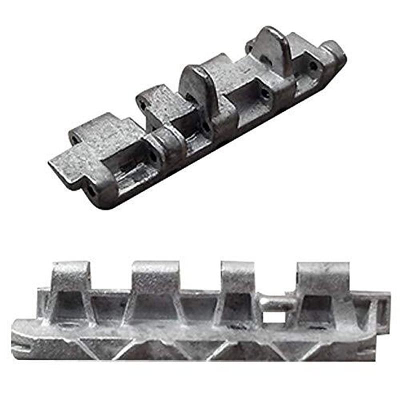
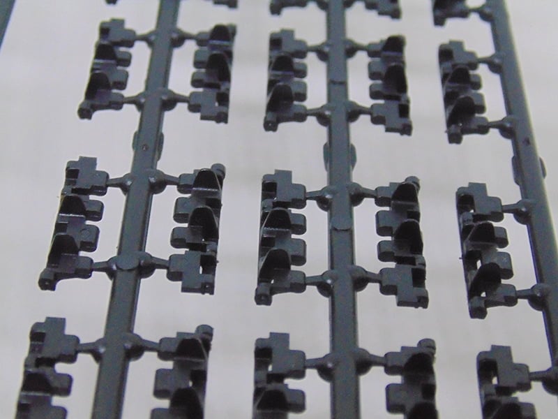
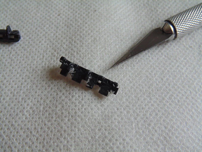
Without any debate the most popular battle tank in history is the German Tiger 1. The model kit is produced by many manufacturers, with Tamiya being one of the most popular. This “mid production” kit has nicely detailed individual track links yet is missing the “lightning holes” in the guide horns. The links also have 4 ejector pin marks per part.
If this sounds like a lot of effort you might ask, “why not buy aftermarket metal or plastic ones?”. Good question, but let me point out a few things. Workable Metal Tracks do cost money of course, the pin holes have to be reamed out to ensure the pin will fit the entire width, then they each have to be washed and scrubbed with soapy water and a tooth brush. After this they have to dry and many people will purchase a burnishing fluid to blacken the surface. The other alternative is plastic workable tracks which require being cut from the sprue and a certain amount of clean up. Regardless of which route you go down there’s going to be some hours put into the work.
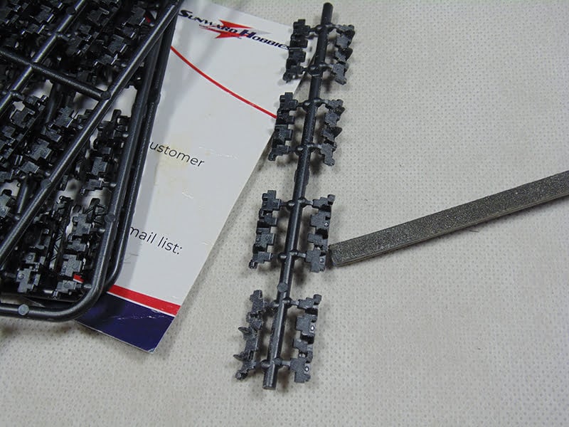
There are several ways to clean up ejector pin marks. You can pick up at the store thin sanding sticks.
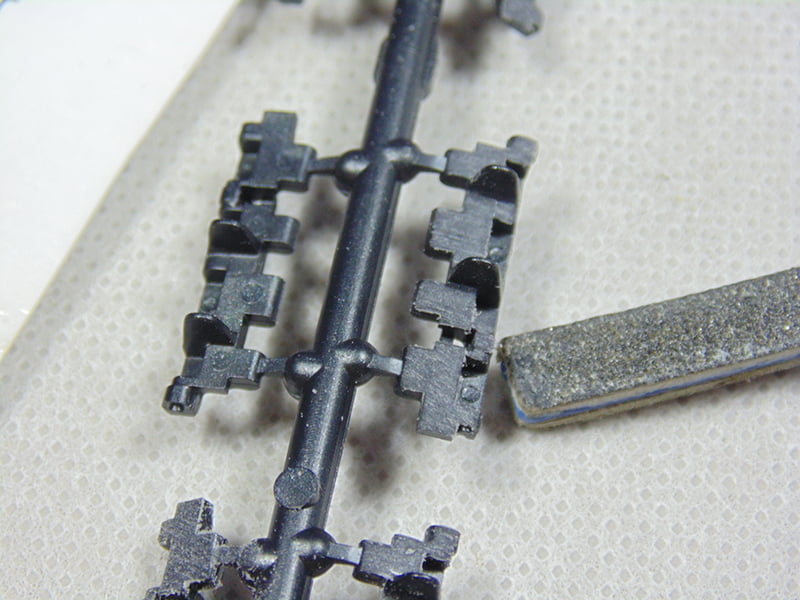
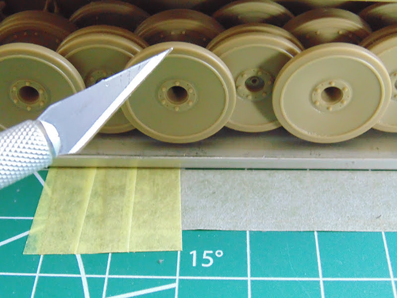
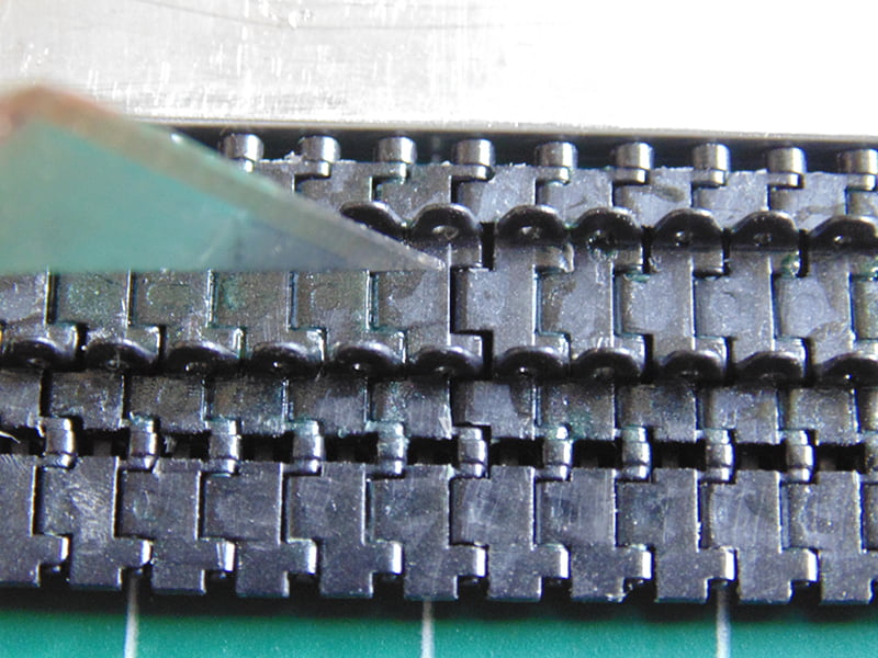
You can buy blades and scrape the material smooth. (more on this later)

Or you may want to fill will mastic then sand smooth.

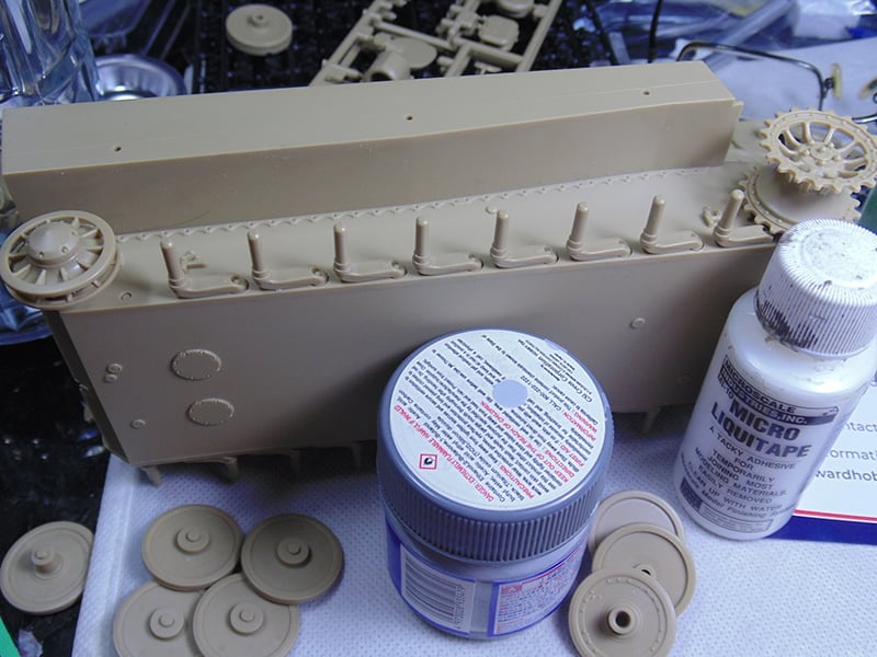
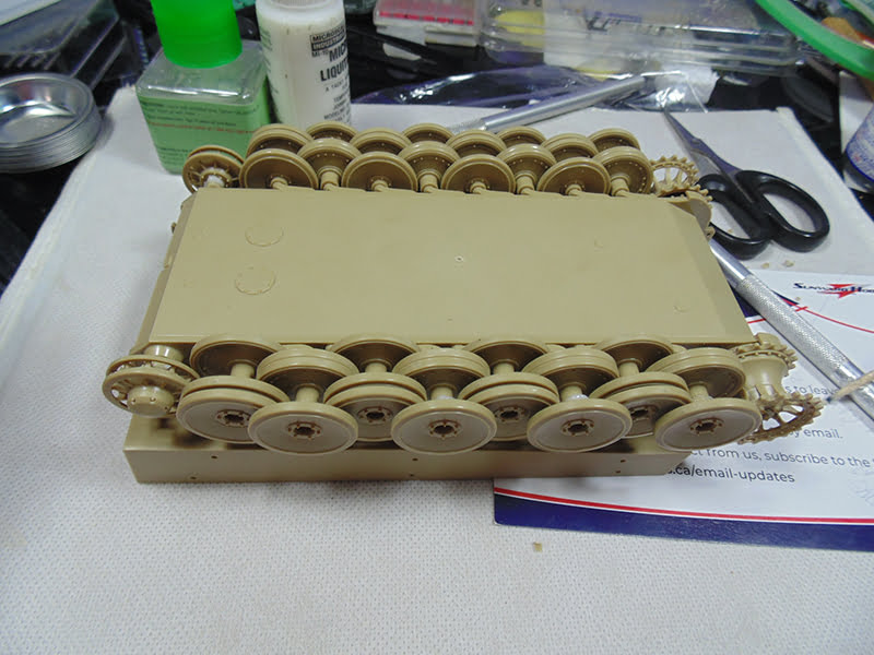
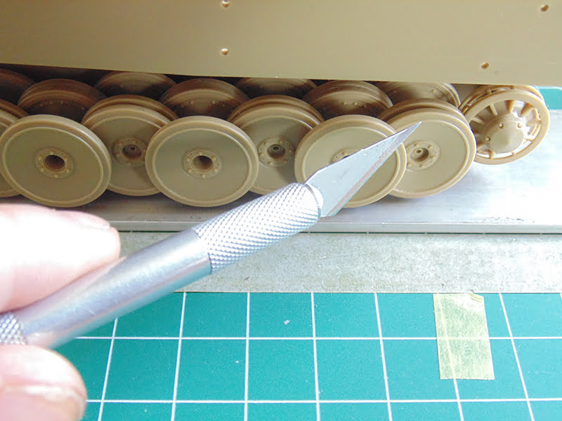
Naturally, you might even want to skip this all together. Regardless, you’ll need to have your idler, road wheels and drive sprocket built up to form your track.
This model will be built later when book I ordered comes in and shows the proper camouflage. The parts will be temporarily joined with Microscale Liquitape MI-10. An awesome product for many tasks and perfect for this one.
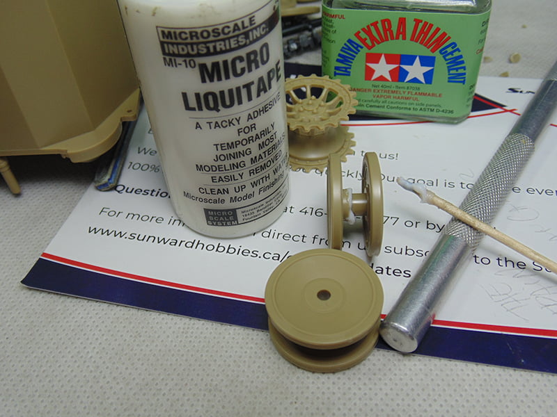
Use it very sparingly though on the idler and drive sprocket since you’ll need to turn them a little when the track goes on.
Let this dry for a solid day. The parts will still move or flex but it’s definitely strong enough to work with. Besides the parts had to be cleaned up anyway.
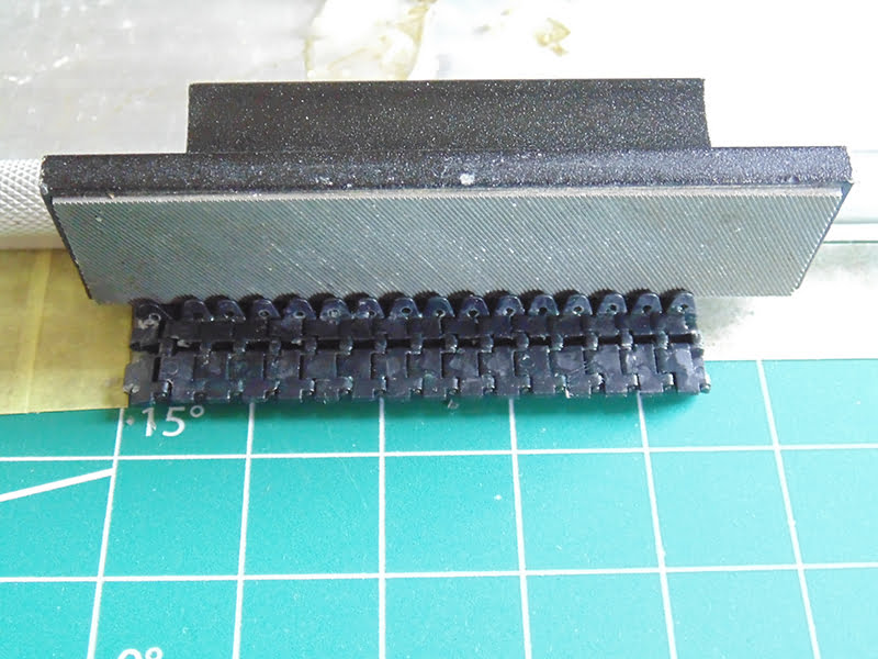
When cleaning up your track links my suggestion is to snip them with a little of sprue gate remaining. Next get your side cutters even closer, yet not flush with the part. If you are that close there’s a risk of the jaws pulling material from the part.
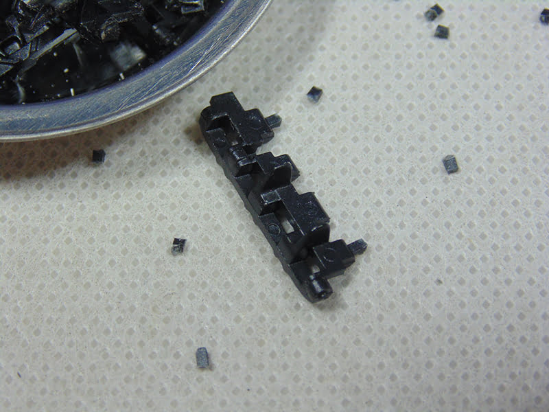
It’s much wiser to leave a little nub and sand that back where you have much more control.
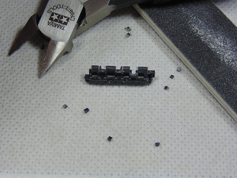
Tamiya have excellent tolerances in their parts engineering, so go by what you see they’ve made to know when to stop sanding.
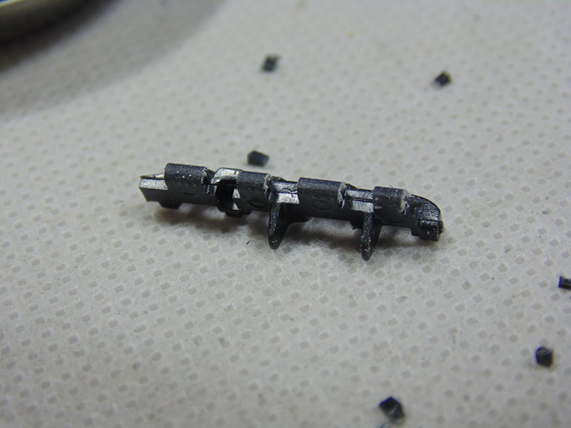
Next on the list to look after are the guide horns. Pick an appropriate width of drill bit and center it on the inside horn and twist. You can use a power tool for this but I find having more control prevents mishaps. Besides the plastic is soft it takes only a few turns to break through. Then line up to the next horn. After you’re through give it a few more twists. I’ve seen pictures of round and rectangular holes, so don’t sweat it if they’re not perfect.
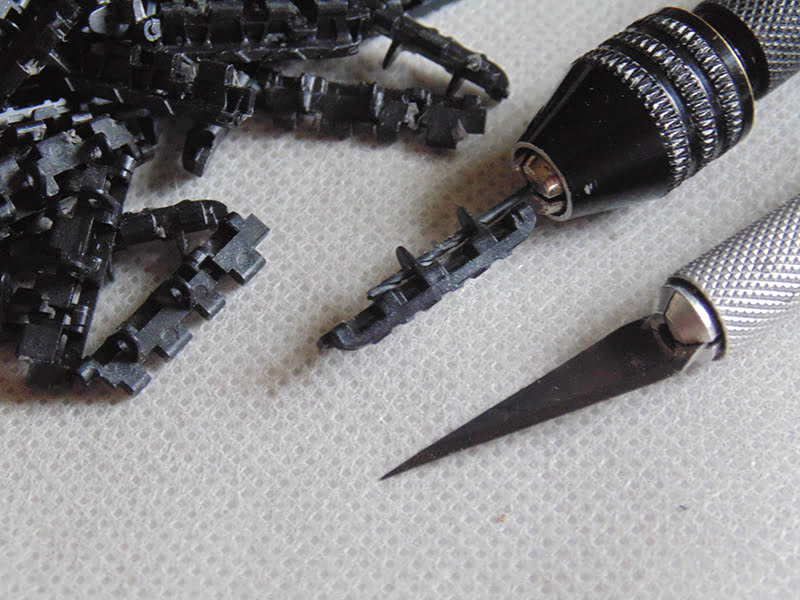
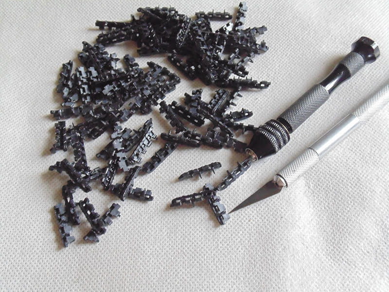
Put on some music or a few podcasts and you’ll be shocked how quickly and automatically the work flows. My method was simple and repetitive. Grab a link, drill, put the drill down and pick up the blade and scrape the 4 ejector pin marks. Rinse and repeat.
You’ll get some fuzz from the scraping but DO NOT remove this. You’ll see soon why it’s going to help.
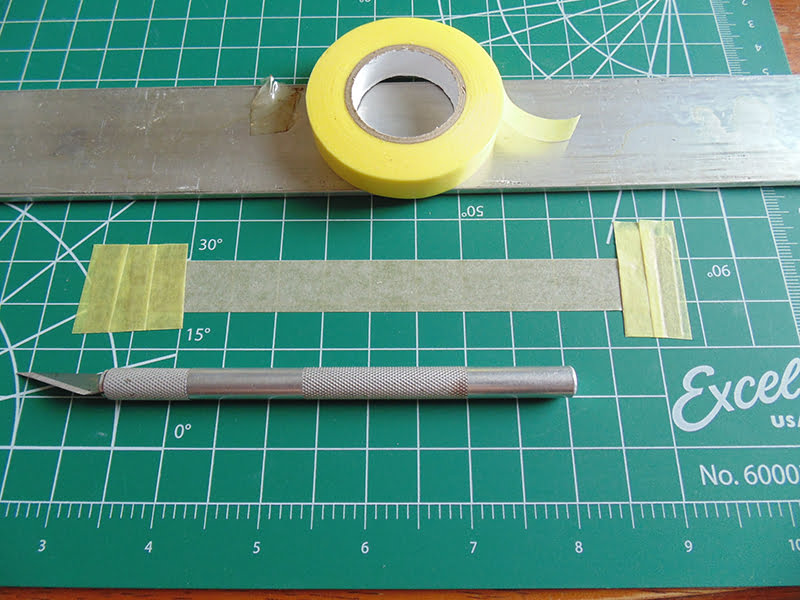
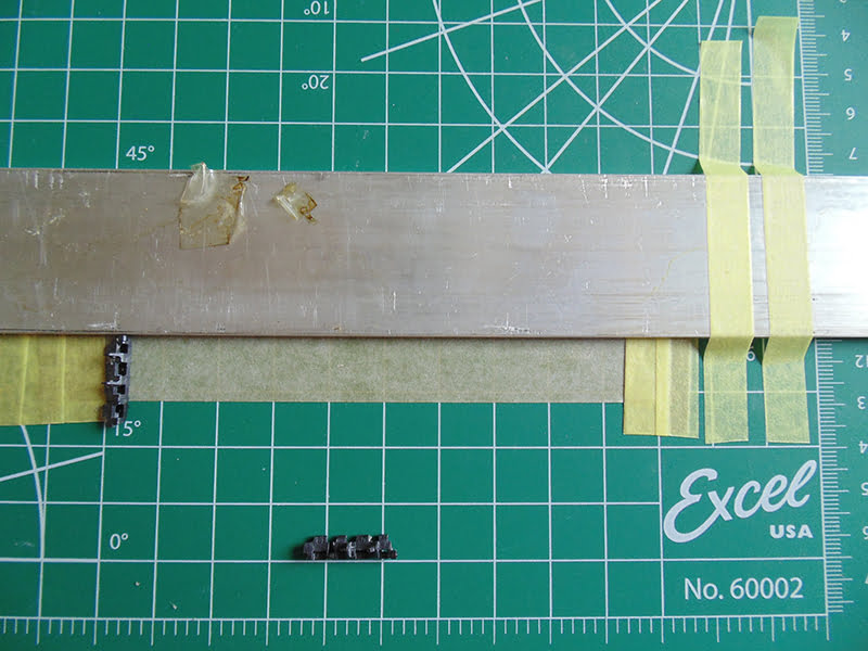
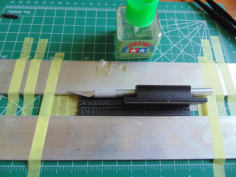
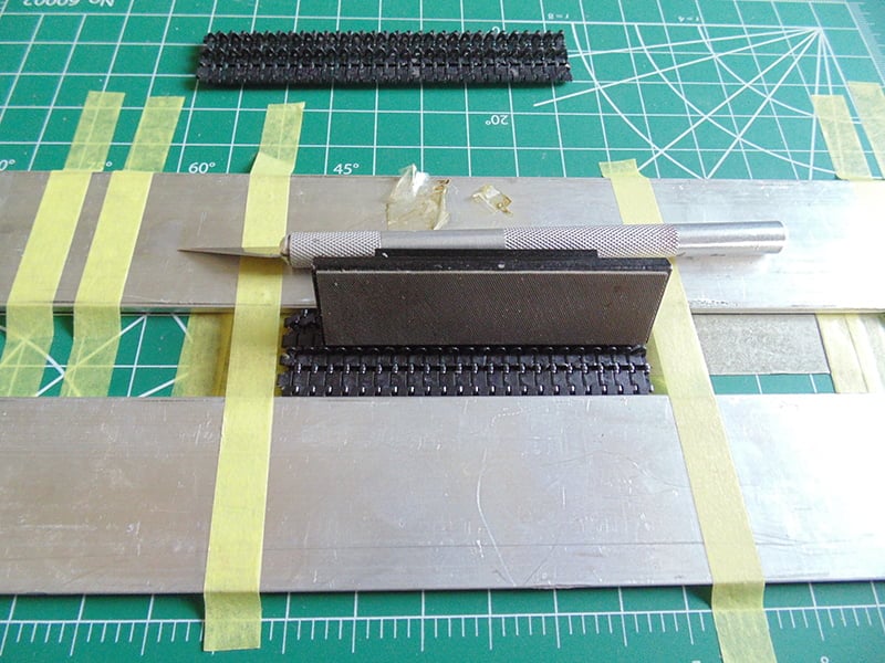
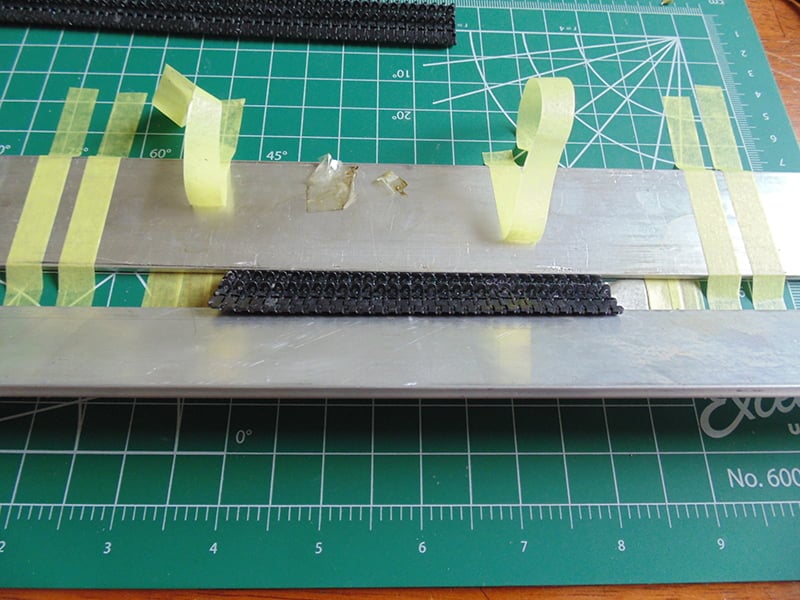
Now we’ll begin assembling the tracks by building in sections. You’ll need a couple of straight edges and some masking tape. Here I’m using Mr. Hobby brand but Tamiya or any of the others you can buy at the store will work just fine. Place a length sticky side up and secure it. I recommend picking up a small cutting mat like the one here I recently bought. They’re supper handy for small jobs plus you can move the work to where it’s more convenient for watching TV or enjoying an evening on the balcony.
We’re going to measure out a specific length or run of track. However, the first link is not glued to the next. The only reason it’s there is to prop up the next. Note how it droops yet the next one stay level, this is why. Also, the tape is to keep the links from flying away when you place and cement them.
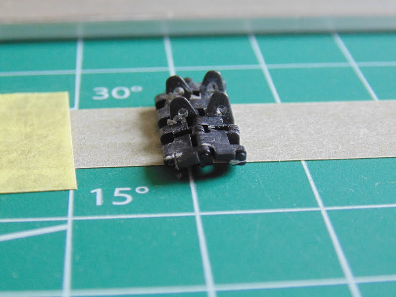
With this length it has to begin where there will not be any bend. In this case it’s directly under the front road wheel and carry on to the back road wheel which will not have any bend. In other words, a straight run. Again, this why I built up the suspension and road wheels.
The straight edge should be something with a bit of weight but it’s always a good idea to secure to your cutting mat at both ends.
Begin connecting the links with some tweezers as tight as possible to the previous and let the tape hold them.
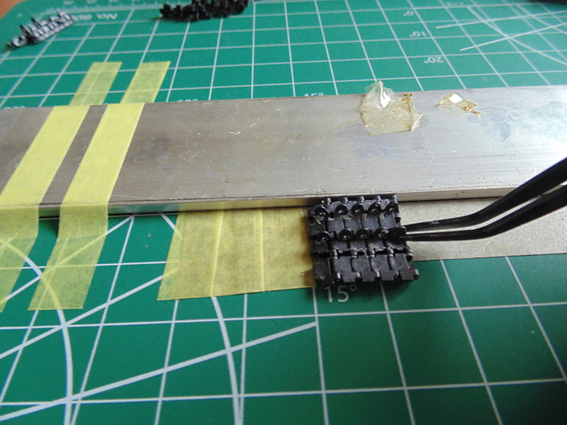
I prefer to work in groups of 5. This way your eyes won’t get confused as to if you’ve cemented a link or not. Having another straight edge to flatten them is a must.
Now you can see why that fuzz from scrapping comes in handy. It’s super easy to see what was cemented and what wasn’t. Again, go by units of 5.
La Tamiya Extra Thin Cemenet is idea for this work. If you take the entire brush full and touch in the center of the link it will wick along the seams and melt most of that excess plastic. Then you can easily brush the rest to melt it into the part. You should also run a brush over your hollowed out guide horns to make the holes look more rounded.

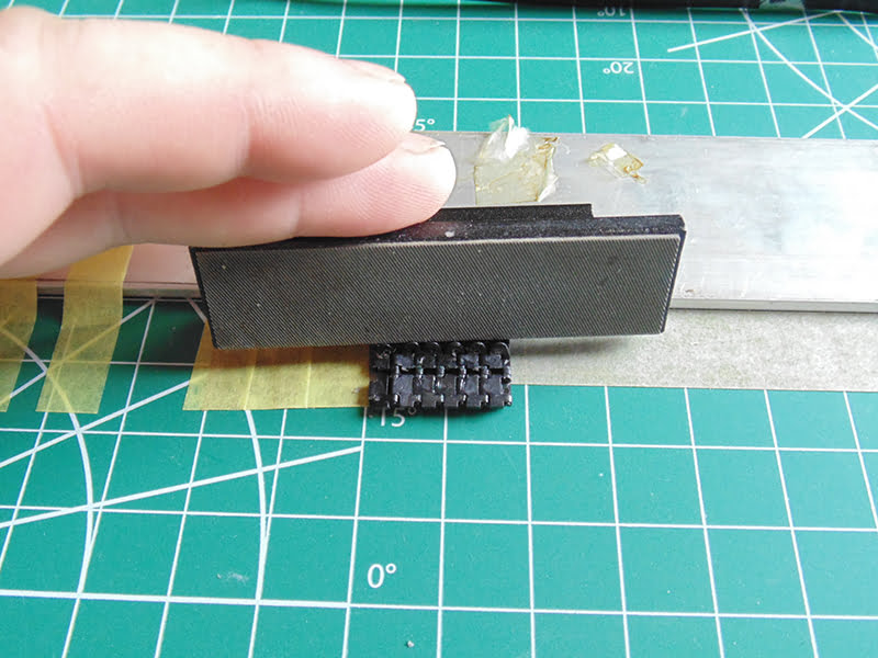
Once again use your straight edge to flatten and push them tight up to the other straight edge. A little tip is not to use a plastic straight edge as it may stick to the track links.
When you get to a point where the run of links is long it’s vital to ensure the entire run is straight. Not every link is going to fit the same way. Bring in a third straight edge, butt it up tight and then secure it. Use the flattener to perfect the run. Don’t be afraid to use some more cement to loosen up crooked ones and then push them together properly.
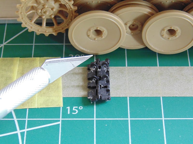
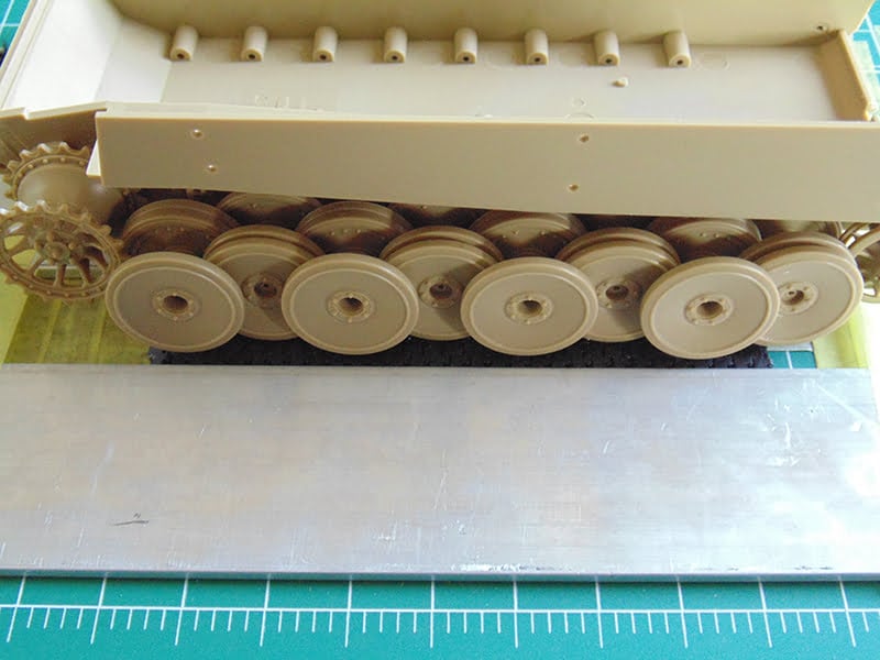
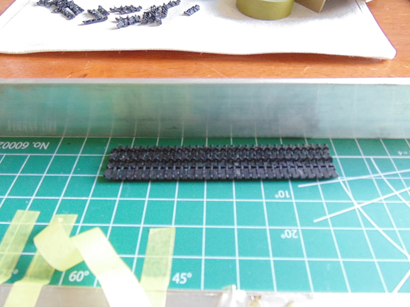
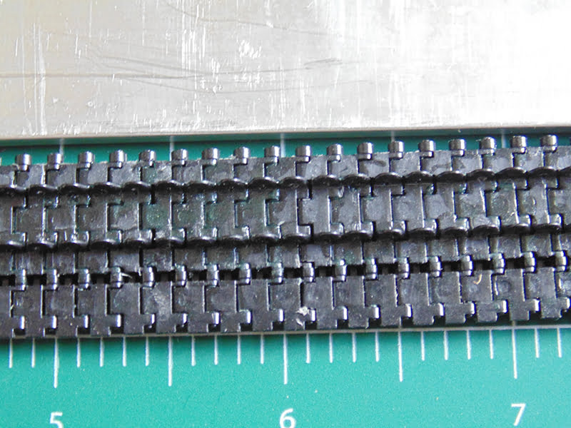
Here’s the length of tracks under the road wheels. It’s a good idea to let this sit for an hour.
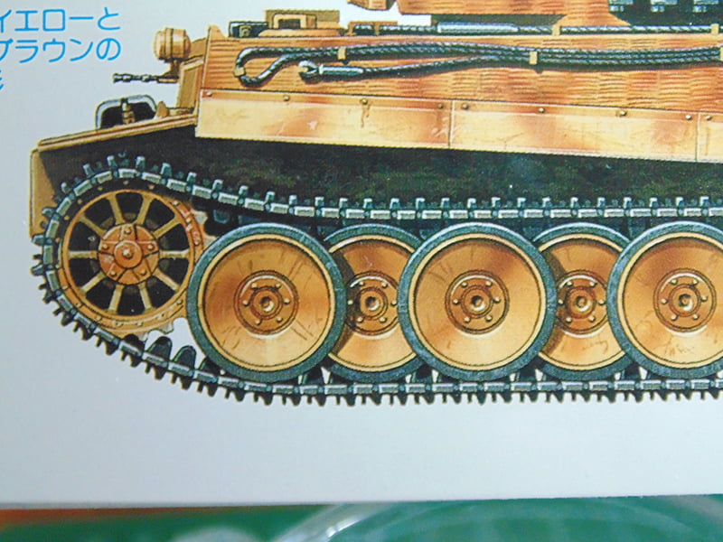
Next, we’ll work out where to do a top run. I’ll use the third road wheel set to begin another straight run back to the last set of wheels. You can see from the box art that the tracks don’t touch until the second set of wheels. This is accurate.
The length, as with the bottom, begins in the middle of the road wheel and at the start of the sticky tape.
We’ll end at the last set of wheels because I’m going to make a separate run to form around the idler and connect up with the bottom run.
Here’s another tip. If the length of straight run is going to sit for any length of time and not be worked on, place a flat weighted object on it. The cement will shrink as it dries and this will help prevent it from
warping.
Now that the second run is complete you can check for alignment continuity. While these parts do not connect it a good idea fix this now so they do connect correctly with ones they slip into.
You can see there is a slight gap at one side.
You can easily correct this by twisting the run while the cemented plastic is still soft. You can also remove some of the material from a part to fix this if the parts are going to connect directly. That wasn’t the case here, it’s just another tip. You can see now that the alignment is great preventing issues with other connecting parts.
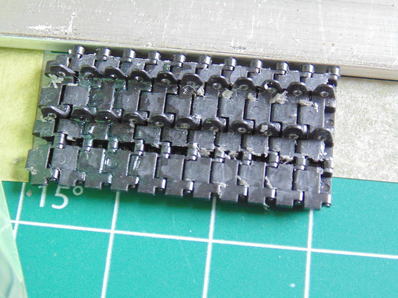
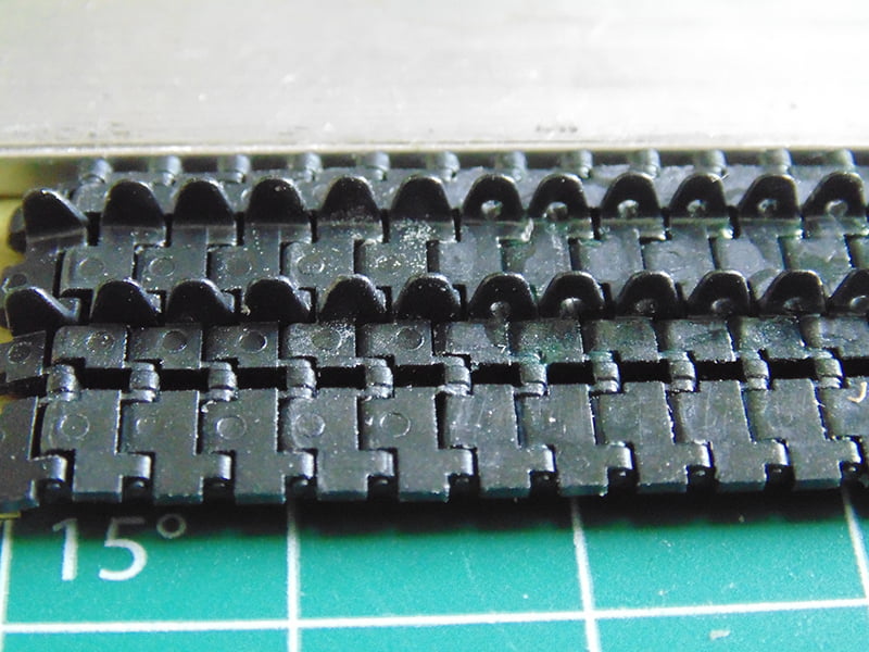
Angelo wanted me to show the difference between improved and straight out of the box links. The way they go together is identical. Clearly you can see the difference here.
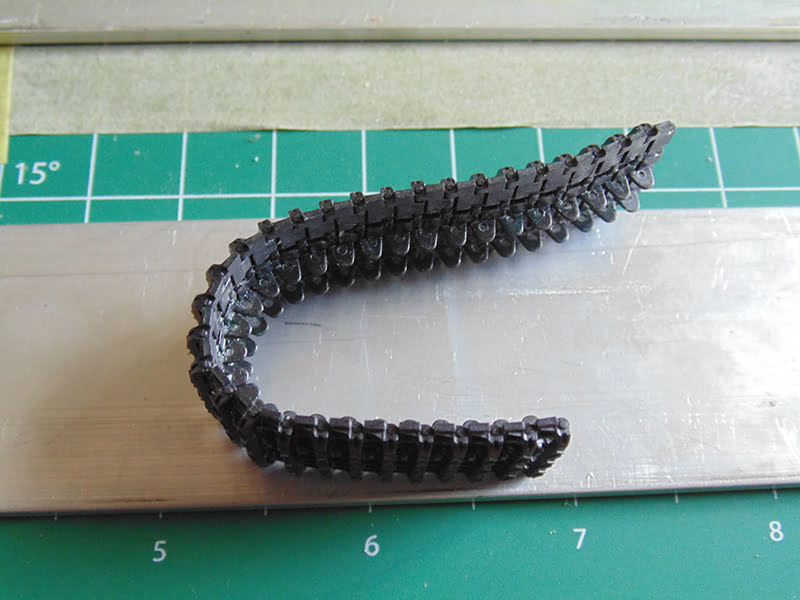
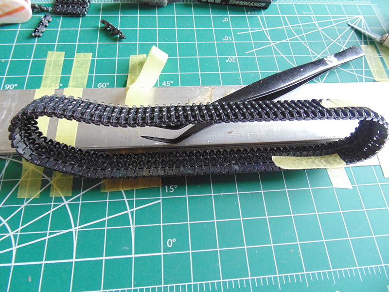
Now the curved ends can be made. Place all the links down, in this case I guessed about 30. They should be put in your jig and cemented at the same time. Work them together tight and let sit for about 15 minutes. They will stay connected, yet are very flexible. Carefully lift the entire run from one side off the tape.
Roughly form this flexible run into the shape of the drive sprocket.
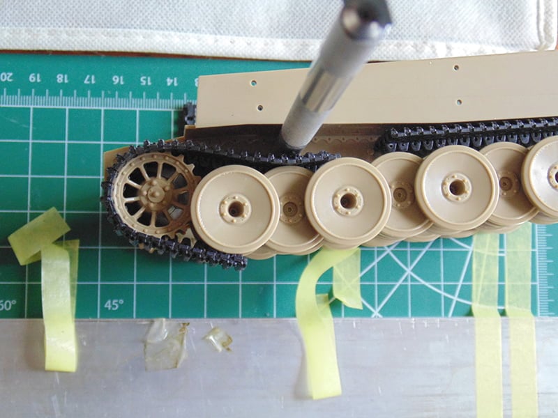
Form this around the sprocket and use a tool to hold down to the correct road wheel while forming it to the bottom wheel.
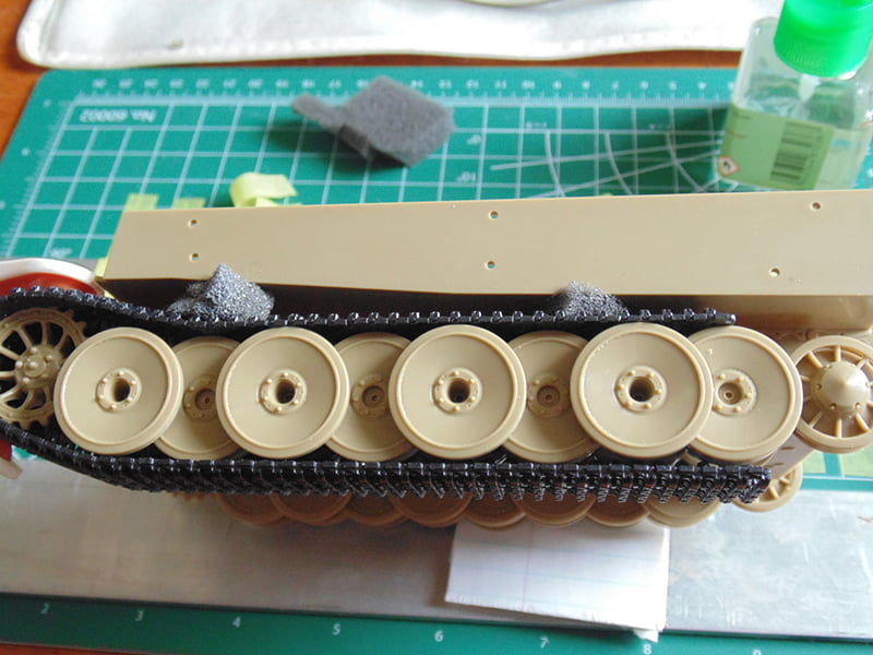
Now you can attach the lower run. Use a clamp or cloths pin to keep it in place while the lower section is setting up. A bit of sponge works wonders to keep the shape of the sag correct.
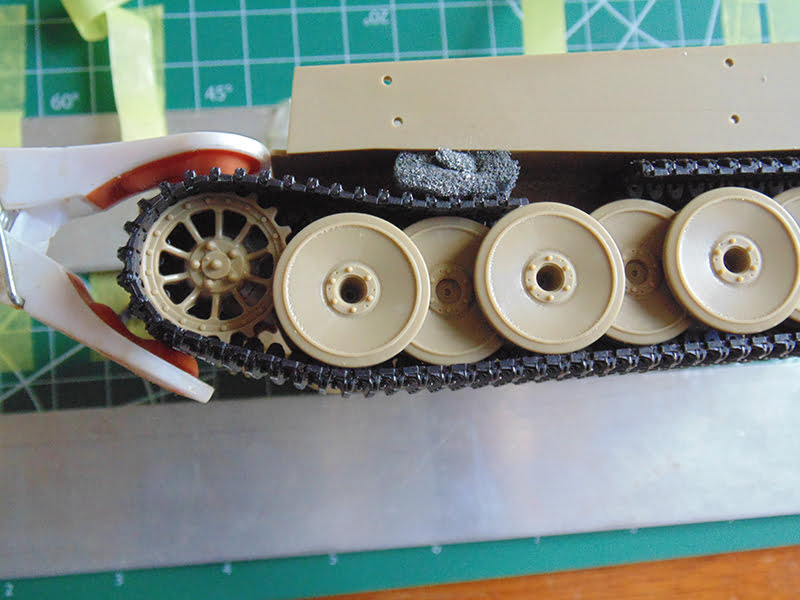
Make sure your clamp is dead on to keep the angle right. Remember the cement is still a long way from hardening and can get misshaped easily.
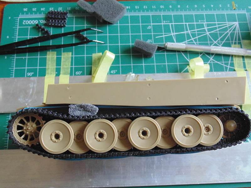
Now the upper section can get cemented. It slides in easily enough but some sponge stuffed in the full width will keep it flat. Always a good idea to continually check this. Use your tweezers to jam the two connecting points tight.
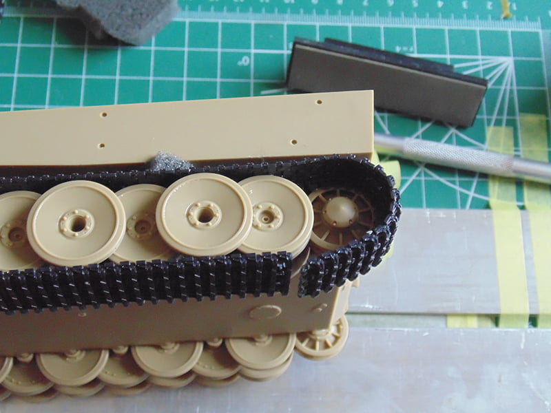
The idler section takes about 20 links but I always add a few more. Connect the top and cement, letting it sit for 15 minutes to set up. Then form this length around the idler and down. Remove any extra links and connect the bottom.
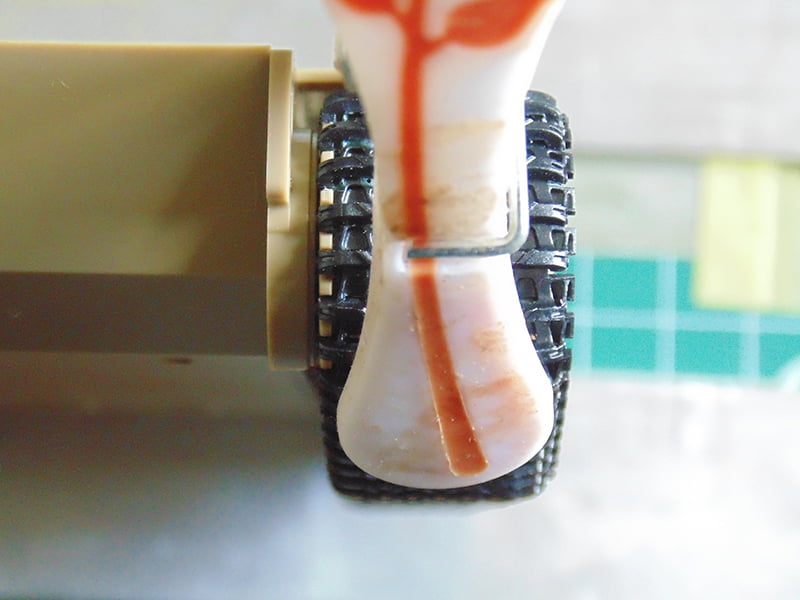
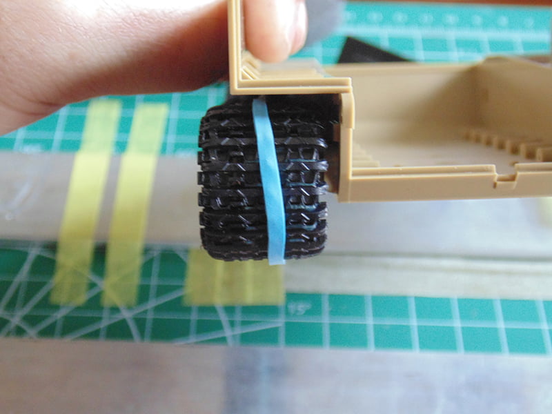
For some added reinforcement use a rubber band to wrap around the entire track while the cement continues to cure. Make certain your sag point has some pressure as well.
As with the clamp that front, center the rubber band so the track has the correct angle.
After the track has dried for a day you can remove it by opening up the gap at the rear and gently lifting it off the wheels. It’s now ready to prime and paint as you see fit. To reinstall simply work it over your painted road wheels, idler and drive sprocket. Since the cement is now hardened the track is strong yet still flexible.
Thanks for following along and as always if you have any questions please ask when placing your order. Have fun with your hobby.
H.G. Barnes is a former voice-over artist and retired sales and marketing professional. He’s the author of two large volume science fiction adventure romance novels with many more in the works. For well over 40 years he’s been building scale model replicas and now does commission work for clients in Canada and the USA, plus completes projects for companies in Asia and Europe.
Actuellement, HG est impliqué en tant que rédacteur associé avec les chaînes de magazines en ligne de KitMaker Network.